Disassembly Procedures
!WARNING
To avoid risk of electrical shock, personal injury or death; disconnect power to unit before servicing.
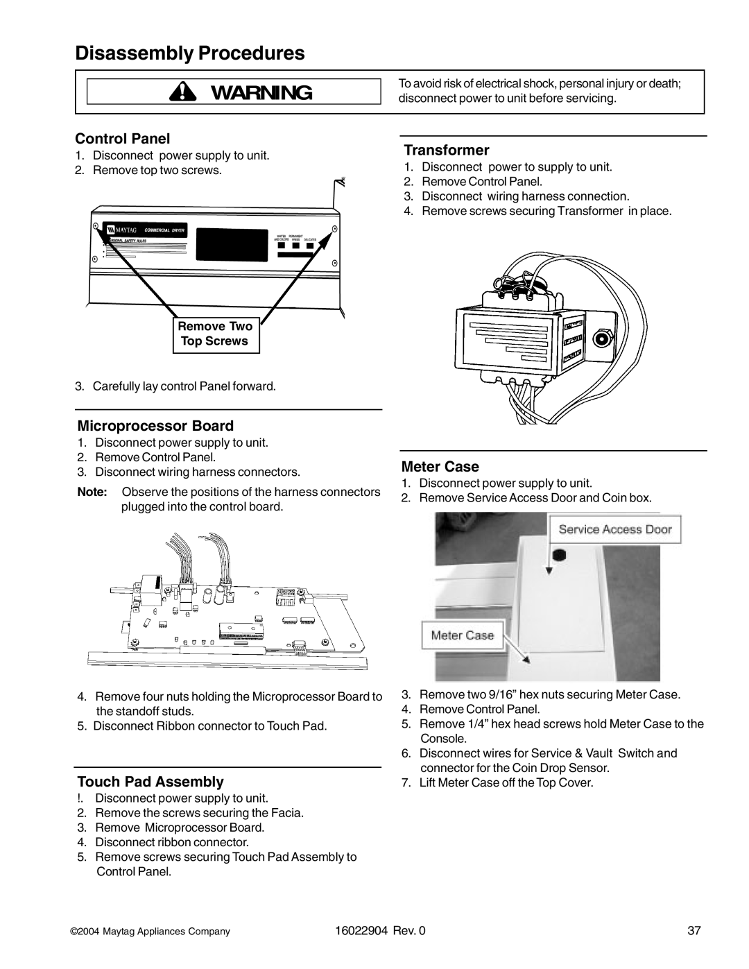
Control Panel
1.Disconnect power supply to unit.
2.Remove top two screws.
Remove Two
Top Screws
3. Carefully lay control Panel forward.
Microprocessor Board
1.Disconnect power supply to unit.
2.Remove Control Panel.
3.Disconnect wiring harness connectors.
Note: Observe the positions of the harness connectors plugged into the control board.
4.Remove four nuts holding the Microprocessor Board to the standoff studs.
5.Disconnect Ribbon connector to Touch Pad.
Touch Pad Assembly
!. Disconnect power supply to unit.
2.Remove the screws securing the Facia.
3.Remove Microprocessor Board.
4.Disconnect ribbon connector.
5.Remove screws securing Touch Pad Assembly to Control Panel.
Transformer
1.Disconnect power to supply to unit.
2.Remove Control Panel.
3.Disconnect wiring harness connection.
4.Remove screws securing Transformer in place.
Meter Case
1.Disconnect power supply to unit.
2.Remove Service Access Door and Coin box.
3.Remove two 9/16” hex nuts securing Meter Case.
4.Remove Control Panel.
5.Remove 1/4” hex head screws hold Meter Case to the Console.
6.Disconnect wires for Service & Vault Switch and connector for the Coin Drop Sensor.
7.Lift Meter Case off the Top Cover.
©2004 Maytag Appliances Company | 16022904 Rev. 0 | 37 |
