General Information
HOW IT WORKS
The cycles are made up of three basic operations. White & Colors, Permanent Press and Delicates and Knits. These operation are sequenced by the controls (timer or microprocessor board) to provide a drying cycle for each of several different fabrics.
Incoming air is pulled over and around the exterior of the rotating tumbler. The air passing over the tumbler is preheated from the warm tumbler. This incoming air also passes over the inside of the cabinet lowering the cabinets temperature and minimizing the heat being dispelled into the laundry area.
The
The heated air is pulled up the stack and through the grid in the tumbler back, through the tumbler, and to the lower area of the tumbler front. The tumbler is rotating in a clockwise direction lifting the
garments to the top of the tumbler. The garments fall free of the clothes lifters through the air stream. As this tumbling takes place, the garments keep turning over within the tumbler. Moisture is evaporated from the garments tumbling in the warm, dry air.
After passing through the garments, the air will contain moisture and lint. This air is pulled from the tumbler through a fine mesh filter located in the bottom of the door opening. The quantity of lint collected on the filter is dependent upon the size and type of load being dried.
From the filter, the air is pulled into the exhaust blower and forced out the exhaust system. The high speed blower is capable of moving up to 220 CFM of air. The volume of the tumbling chamber is approximately 6.0 cubic feet.
GAS VALVE ASSEMBLY
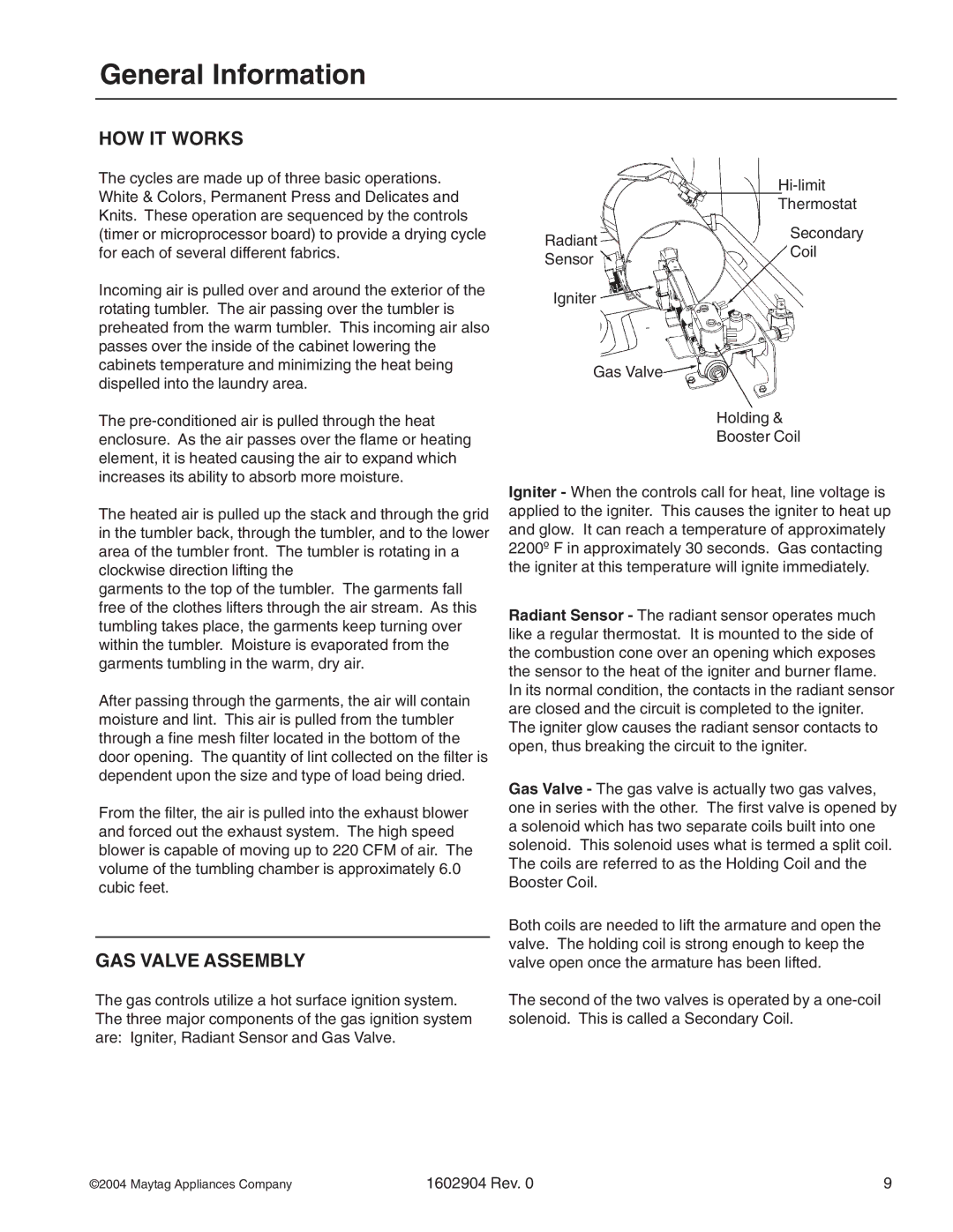
The gas controls utilize a hot surface ignition system. The three major components of the gas ignition system are: Igniter, Radiant Sensor and Gas Valve.
| ||
| Thermostat | |
Radiant | Secondary | |
Coil | ||
Sensor | ||
| ||
Igniter |
|
Gas Valve
Holding &
Booster Coil
Igniter - When the controls call for heat, line voltage is applied to the igniter. This causes the igniter to heat up and glow. It can reach a temperature of approximately 2200º F in approximately 30 seconds. Gas contacting the igniter at this temperature will ignite immediately.
Radiant Sensor - The radiant sensor operates much like a regular thermostat. It is mounted to the side of the combustion cone over an opening which exposes the sensor to the heat of the igniter and burner flame.
In its normal condition, the contacts in the radiant sensor are closed and the circuit is completed to the igniter. The igniter glow causes the radiant sensor contacts to open, thus breaking the circuit to the igniter.
Gas Valve - The gas valve is actually two gas valves, one in series with the other. The first valve is opened by a solenoid which has two separate coils built into one solenoid. This solenoid uses what is termed a split coil. The coils are referred to as the Holding Coil and the Booster Coil.
Both coils are needed to lift the armature and open the valve. The holding coil is strong enough to keep the valve open once the armature has been lifted.
The second of the two valves is operated by a
©2004 Maytag Appliances Company | 1602904 Rev. 0 | 9 |
