TABLE OF CONTENTS
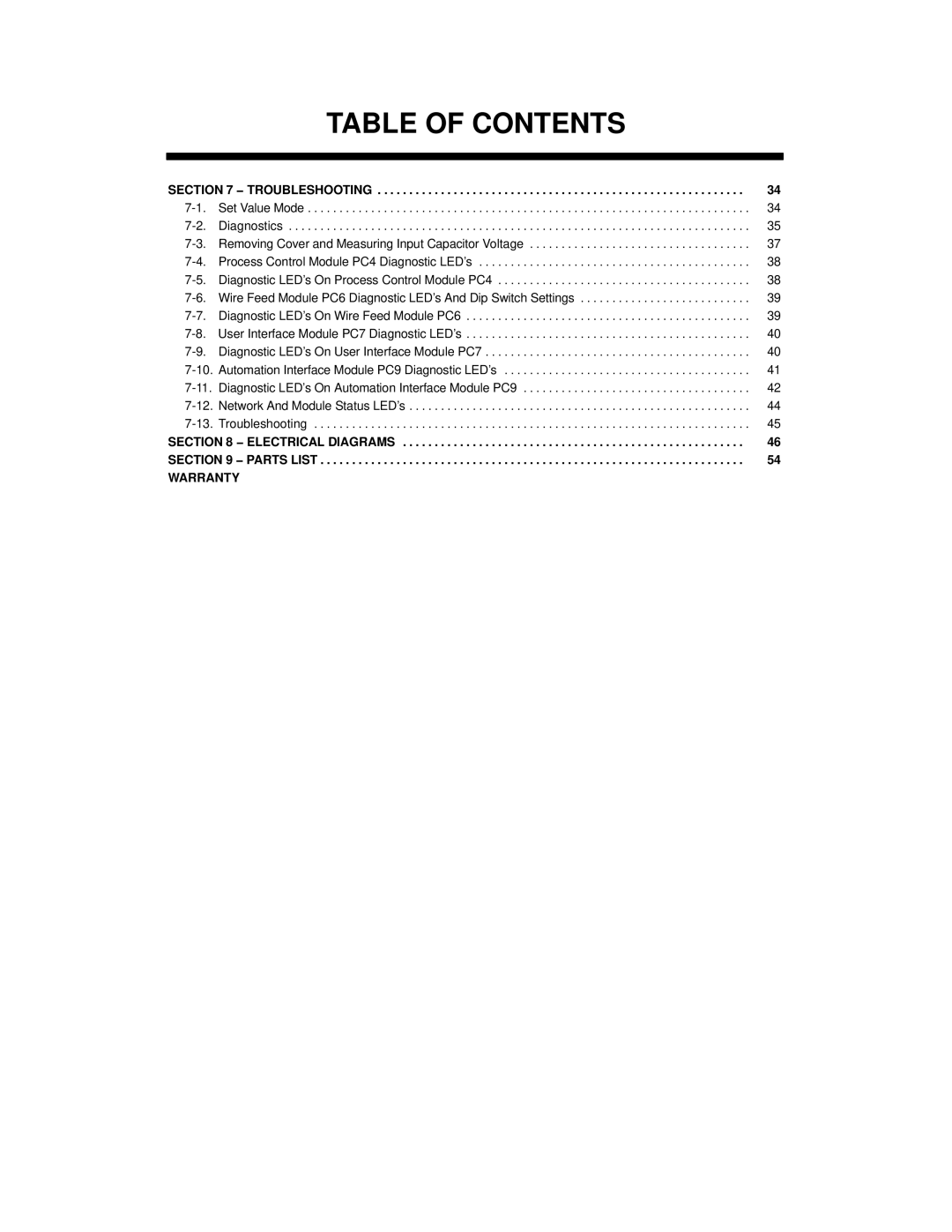
SECTION 7 − TROUBLESHOOTING | 34 | |
Set Value Mode | 34 | |
Diagnostics | 35 | |
Removing Cover and Measuring Input Capacitor Voltage | 37 | |
Process Control Module PC4 Diagnostic LED’s | 38 | |
Diagnostic LED’s On Process Control Module PC4 | 38 | |
Wire Feed Module PC6 Diagnostic LED’s And Dip Switch Settings | 39 | |
Diagnostic LED’s On Wire Feed Module PC6 | 39 | |
| 40 | |
Diagnostic LED’s On User Interface Module PC7 | 40 | |
Automation Interface Module PC9 Diagnostic LED’s | 41 | |
Diagnostic LED’s On Automation Interface Module PC9 | 42 | |
Network And Module Status LED’s | 44 | |
Troubleshooting | 45 | |
SECTION 8 − ELECTRICAL DIAGRAMS | 46 | |
SECTION 9 − PARTS LIST | 54 | |
WARRANTY |
| |
