7-3. Removing Cover and Measuring Input Capacitor Voltage
! | 900 Volts dc can be present on the capacitor bus and | |
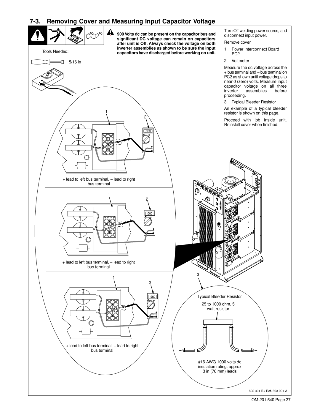
| significant DC voltage can remain on capacitors | |
| after unit is Off. Always check the voltage on both | |
Tools Needed: | inverter assemblies as shown to be sure the input | |
capacitors have discharged before working on unit. | ||
| ||
5/16 in |
|
Turn Off welding power source, and disconnect input power.
Remove cover
1Power Interconnect Board PC2
2Voltmeter
1
2
+lead to left bus terminal, − lead to right bus terminal
1
2
+lead to left bus terminal, − lead to right bus terminal
1
2
+lead to left bus terminal, − lead to right bus terminal
Measure the dc voltage across the
+bus terminal and − bus terminal on PC2 as shown until voltage drops to near 0 (zero) volts. Measure input capacitor voltage on all three inverter assemblies before proceeding.
3 Typical Bleeder Resistor
An example of a typical bleeder resistor is shown on this page.
Proceed with job inside unit.
Reinstall cover when finished.
3
Typical Bleeder Resistor
25 to 1000 ohm, 5
watt resistor
#16 AWG 1000 volts dc insulation rating, approx 3 in (76 mm) leads
802