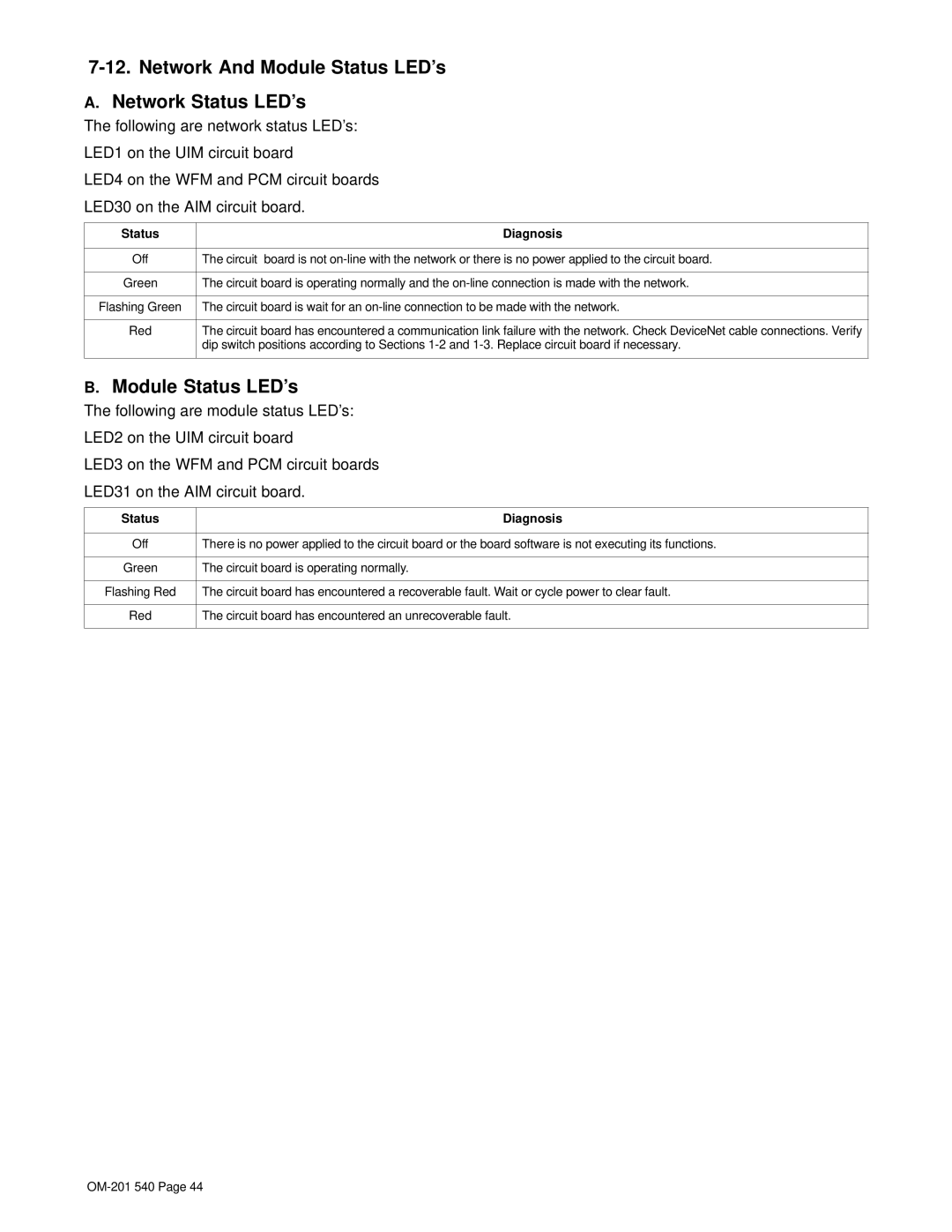
7-12. Network And Module Status LED’s
A.Network Status LED’s
The following are network status LED’s:
LED1 on the UIM circuit board
LED4 on the WFM and PCM circuit boards
LED30 on the AIM circuit board.
Status | Diagnosis |
|
|
Off | The circuit board is not |
|
|
Green | The circuit board is operating normally and the |
|
|
Flashing Green | The circuit board is wait for an |
|
|
Red | The circuit board has encountered a communication link failure with the network. Check DeviceNet cable connections. Verify |
| dip switch positions according to Sections |
|
|
B.Module Status LED’s
The following are module status LED’s:
LED2 on the UIM circuit board
LED3 on the WFM and PCM circuit boards
LED31 on the AIM circuit board.
Status | Diagnosis |
|
|
Off | There is no power applied to the circuit board or the board software is not executing its functions. |
|
|
Green | The circuit board is operating normally. |
|
|
Flashing Red | The circuit board has encountered a recoverable fault. Wait or cycle power to clear fault. |
|
|
Red | The circuit board has encountered an unrecoverable fault. |
|
|
