3-13. Connecting Input Power
3 ![]()
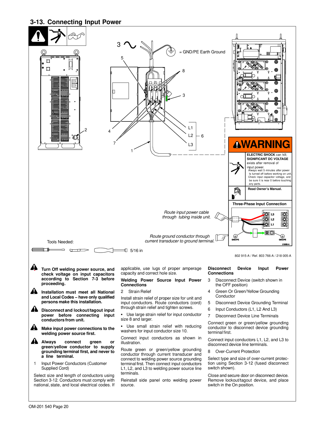
= GND/PE Earth Ground
5
8
3
2 | L1 |
|
4 |
| |
| L2 | 6 |
7 | L3 |
|
1
| Route input power cable |
| through tubing inside unit. |
| Route ground conductor through |
Tools Needed: | current transducer to ground terminal. |
| 5/16 in |
![]() WARNING
WARNING
ELECTRIC SHOCK can kill;
SIGNIFICANT DC VOLTAGE
exists after removal of input power.
SAlways wait 5 minutes after power Is turned off before working on unit.
SCheck input capacitor voltage, and be sure it is near 0 before touching any parts.
Read Owner’s Manual.
802
![]() ! Turn Off welding power source, and check voltage on input capacitors according to Section
! Turn Off welding power source, and check voltage on input capacitors according to Section
![]() ! Installation must meet all National and Local Codes − have only qualified persons make this installation.
! Installation must meet all National and Local Codes − have only qualified persons make this installation.
!Disconnect and lockout/tagout input power before connecting input conductors from unit.
![]() ! Make input power connections to the welding power source first.
! Make input power connections to the welding power source first.
applicable, use lugs of proper amperage capacity and correct hole size.
Welding Power Source Input Power Connections
2 Strain Relief
Install strain relief of proper size for unit and input conductors. Route conductors (cord) through strain relief and tighten screws.
SUse large strain relief for input conductor size 8 and larger.
SUse small strain relief with reducing washers for input conductor size 10.
Disconnect Device Input Power Connections
3Disconnect Device (switch shown in the OFF position)
4Green Or Green/Yellow Grounding Conductor
5Disconnect Device Grounding Terminal
6Input Conductors (L1, L2 And L3)
7Disconnect Device Line Terminals
Connect green or green/yellow grounding conductor to disconnect device grounding terminal first.
! Always connect green or green/yellow conductor to supply grounding terminal first, and never to a line terminal.
1Input Power Conductors (Customer Supplied Cord)
Select size and length of conductors using Section
Connect input conductors as shown in illustration.
Route green or green/yellow grounding conductor through current transducer and connect to welding power source grounding terminal first. Then connect input conductors L1, L2, and L3 to welding power source line terminals.
Reinstall side panel onto welding power source.
Connect input conductors L1, L2, and L3 to disconnect device line terminals.
8
Select type and size of
Close and secure door on disconnect device. Remove lockout/tagout device, and place switch in the On position.