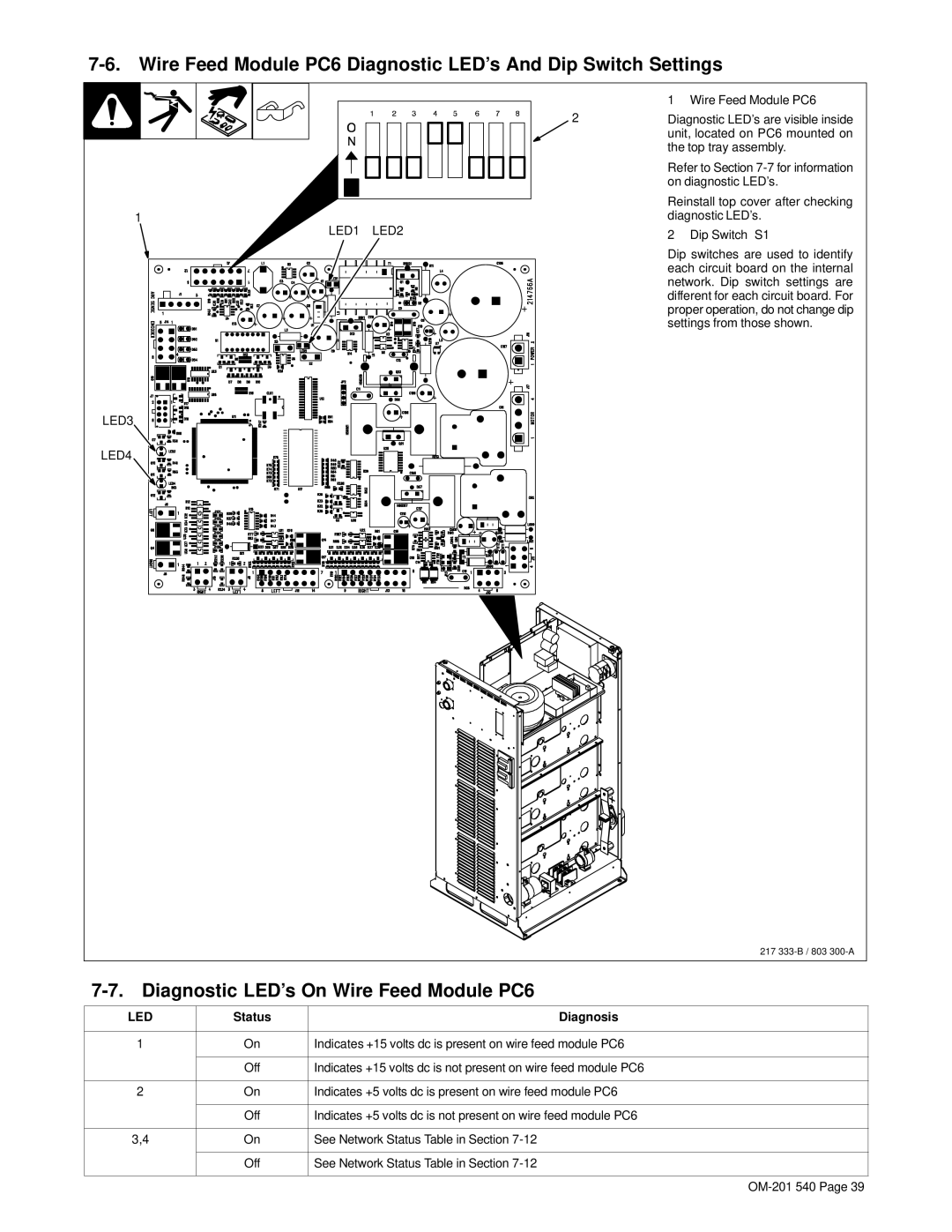
| 1 Wire Feed Module PC6 |
2 | Diagnostic LED’s are visible inside |
| unit, located on PC6 mounted on |
| the top tray assembly. |
| Refer to Section |
| on diagnostic LED’s. |
| Reinstall top cover after checking |
1 | diagnostic LED’s. |
LED1 LED2 | 2 Dip Switch S1 |
| |
| Dip switches are used to identify |
| each circuit board on the internal |
| network. Dip switch settings are |
| different for each circuit board. For |
| proper operation, do not change dip |
| settings from those shown. |
LED3
LED4
217
7-7. Diagnostic LED’s On Wire Feed Module PC6
LED | Status | Diagnosis |
|
|
|
1 | On | Indicates +15 volts dc is present on wire feed module PC6 |
|
|
|
| Off | Indicates +15 volts dc is not present on wire feed module PC6 |
|
|
|
2 | On | Indicates +5 volts dc is present on wire feed module PC6 |
|
|
|
| Off | Indicates +5 volts dc is not present on wire feed module PC6 |
|
|
|
3,4 | On | See Network Status Table in Section |
|
|
|
| Off | See Network Status Table in Section |
|
|
|