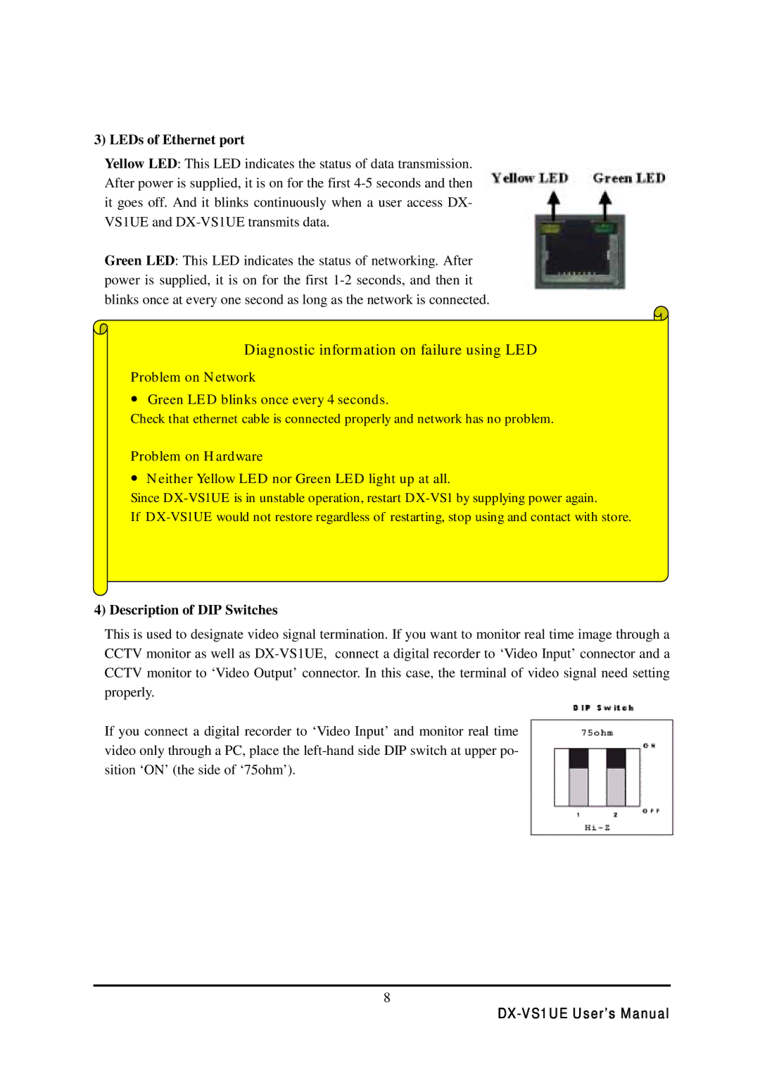
3) LEDs of Ethernet port
Yellow LED: This LED indicates the status of data transmission. After power is supplied, it is on for the first
Green LED: This LED indicates the status of networking. After power is supplied, it is on for the first
Diagnostic information on failure using LED
Problem on Network
•Green LED blinks once every 4 seconds.
Check that ethernet cable is connected properly and network has no problem.
Problem on Hardware
•Neither Yellow LED nor Green LED light up at all.
Since
If
4) Description of DIP Switches
This is used to designate video signal termination. If you want to monitor real time image through a CCTV monitor as well as
If you connect a digital recorder to ‘Video Input’ and monitor real time video only through a PC, place the
8