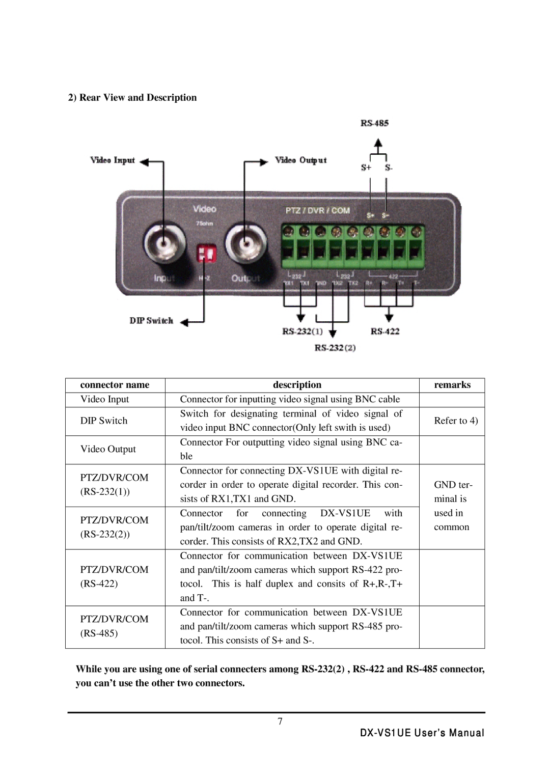
2) Rear View and Description
connector name |
| description | remarks | ||
Video Input | Connector for inputting video signal using BNC cable |
| |||
DIP Switch | Switch for | designating terminal | of video signal of | Refer to 4) | |
video input BNC connector(Only left swith is used) | |||||
|
| ||||
|
|
| |||
Video Output | Connector For outputting video signal using BNC ca- |
| |||
ble |
|
|
| ||
|
|
|
| ||
|
|
| |||
PTZ/DVR/COM | Connector for connecting |
| |||
corder in order to operate digital recorder. This con- | GND ter- | ||||
sists of RX1,TX1 and GND. |
| minal is | |||
|
| ||||
|
|
|
| used in | |
PTZ/DVR/COM | Connector | for connecting | |||
pan/tilt/zoom cameras in order to operate digital re- | common | ||||
corder. This consists of RX2,TX2 and GND. |
| ||||
|
| ||||
|
|
| |||
| Connector for communication between |
| |||
PTZ/DVR/COM | and pan/tilt/zoom cameras which support |
| |||
tocol. This is half duplex and consits of |
| ||||
| and |
|
|
| |
|
|
| |||
PTZ/DVR/COM | Connector for communication between |
| |||
and pan/tilt/zoom cameras which support |
| ||||
| |||||
tocol. This consists of S+ and |
|
| |||
|
|
| |||
|
|
|
|
| |
While you are using one of serial connecters among
7