4.CONNECTIONS
4.7 Communications terminals
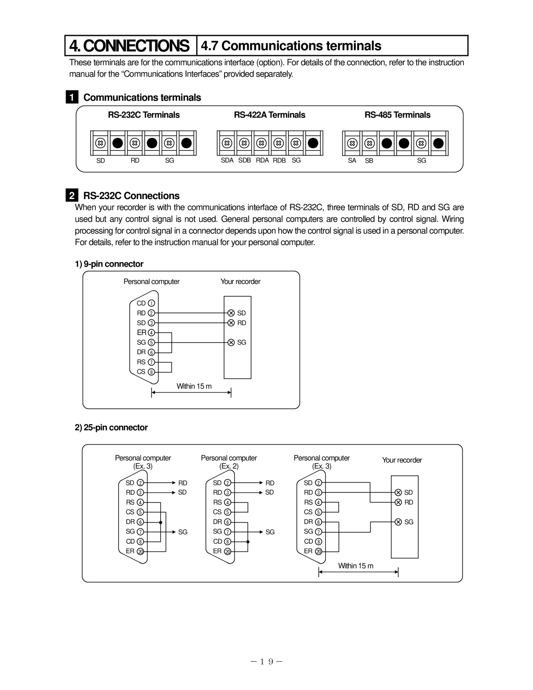
These terminals are for the communications interface (option). For details of the connection, refer to the instruction manual for the “Communications Interfaces” provided separately.
1
Communications terminals
|
|
SD | RD | SG | SDA SDB RDA RDB SG | SA SB | SG |
2
RS-232C Connections
When your recorder is with the communications interface of
1) 9-pin connector
Personal computer | Your recorder |
CD 1
RD 2
SD 3
ER 4
SG 5
DR 6
RS 7
CS 8
Within 15 m
![]() SD
SD ![]() RD
RD
![]() SG
SG
2)
Personal computer | Personal computer | Personal computer | Your recorder |
(Ex. 3) | (Ex. 2) | (Ex. 3) |
|
SD 2 | RD | SD 2 | RD | SD 2 |
RD 3 | SD | RD 3 | SD | RD 3 |
RS 4 |
| RS 4 |
| RS 4 |
CS 5 |
| CS 5 |
| CS 5 |
DR 6 |
| DR 6 |
| DR 6 |
SG 7 | SG | SG 7 | SG | SG 7 |
CD 8 |
| CD 8 |
| CD 8 |
ER 20 |
| ER 20 |
| ER 20 |
![]() SD
SD ![]() RD
RD
![]() SG
SG
Within 15 m
-19-