21. MAINTENANCE
21.3 Measured Values Check
3
Connections
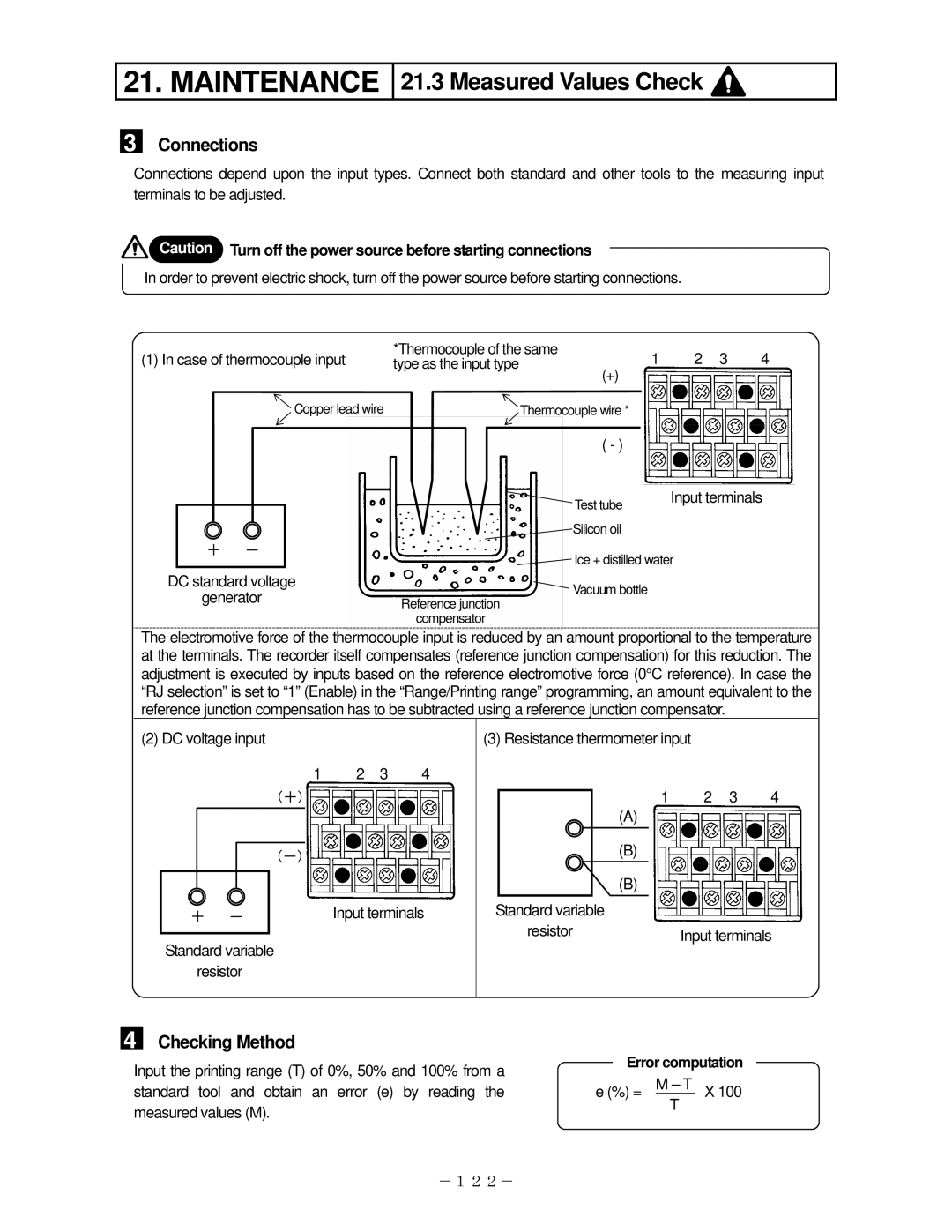
Connections depend upon the input types. Connect both standard and other tools to the measuring input terminals to be adjusted.
![]() Caution Turn off the power source before starting connections
Caution Turn off the power source before starting connections
In order to prevent electric shock, turn off the power source before starting connections.
(1) In case of thermocouple input | *Thermocouple of the same | 1 | 2 3 | 4 | |||||
type as the input type |
| ||||||||
|
|
|
|
|
|
| (+) |
|
|
|
|
| Copper lead wire |
| Thermocouple wire * |
|
| ||
|
|
|
|
|
|
| ( - ) |
|
|
|
|
|
|
|
|
| Test tube | Input terminals | |
|
|
|
|
|
|
|
|
| |
| + | - |
|
|
|
| Silicon oil |
|
|
|
|
|
|
|
|
| |||
|
|
|
| Ice + distilled water |
| ||||
|
|
|
|
|
|
|
| ||
DC standard voltage |
|
| Vacuum bottle |
|
| ||||
| generator | Reference junction |
|
|
| ||||
|
|
|
|
| |||||
compensator
The electromotive force of the thermocouple input is reduced by an amount proportional to the temperature at the terminals. The recorder itself compensates (reference junction compensation) for this reduction. The adjustment is executed by inputs based on the reference electromotive force (0°C reference). In case the “RJ selection” is set to “1” (Enable) in the “Range/Printing range” programming, an amount equivalent to the reference junction compensation has to be subtracted using a reference junction compensator.
(2) DC voltage input
1 2 3 4
(+)
(-)
+ - | Input terminals |
Standard variable
resistor
(3)Resistance thermometer input
12 3 4
(A)
| (B) |
| (B) |
Standard variable |
|
resistor | Input terminals |
4
Checking Method
Input the printing range (T) of 0%, 50% and 100% from a |
| Error computation | |||
e (%) = | M – T | X 100 | |||
standard tool and obtain an error (e) by reading the | |||||
measured values (M). |
|
| T |
| |
|
|
|
| ||
-122-