3. CONFIGULATION
3.2 Display
RD200
CH 1 | CH 2 | CH 3 | CH 4 |
|
|
| (1) |
|
|
| (2) |
CH 1 |
|
| (3) |
CH 2 |
|
| |
|
| (4) | |
CH 3 |
|
|
CH 4
RD2800
| CH 1 | CH 2 | CH 3 | CH 4 | CLOCK CHART SPPED | |
CH 1 |
|
|
|
|
| (1) |
|
|
|
|
| (2) | |
CH 2 |
|
|
|
|
| (3) |
CH 3 |
|
|
| (4) | ||
|
|
|
|
| ||
CH 4
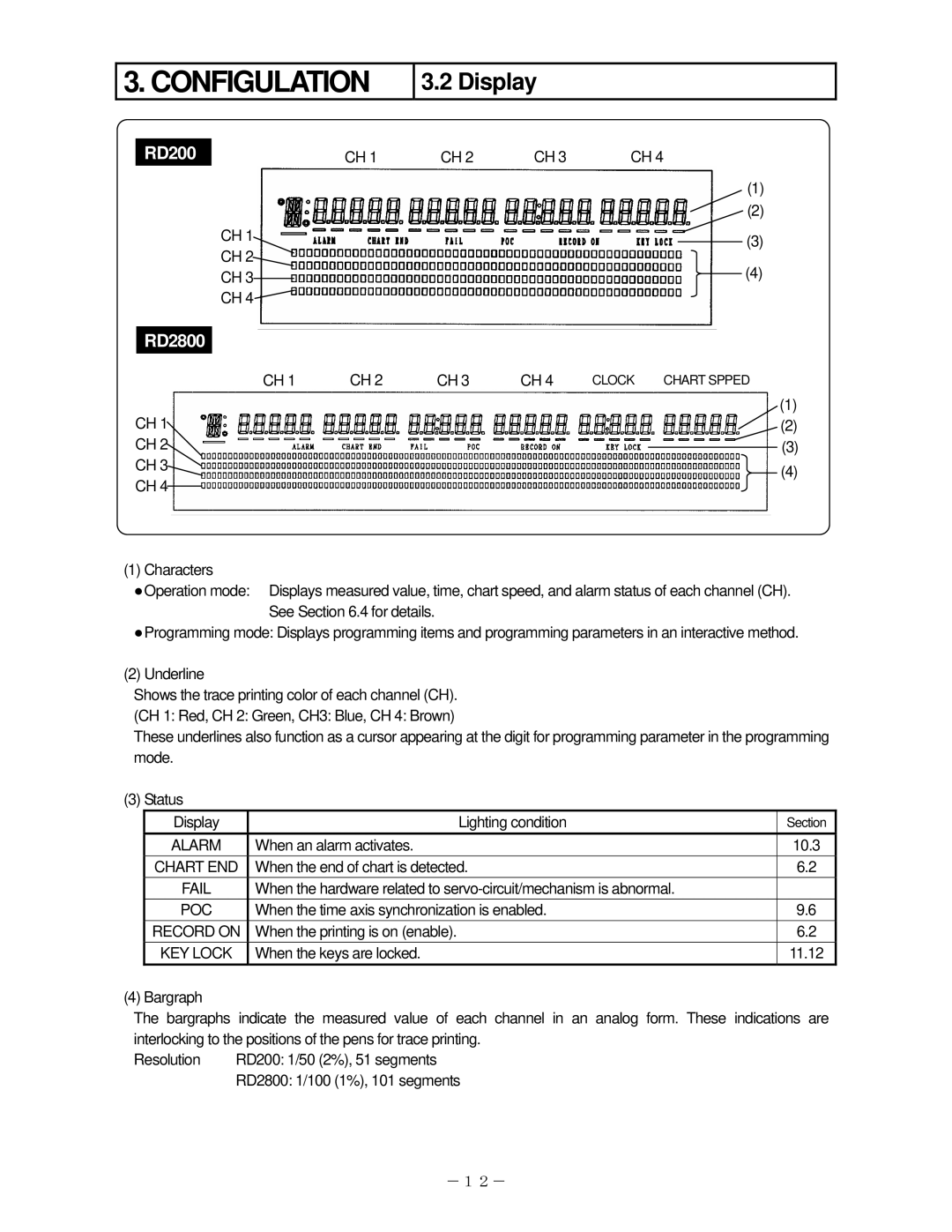
(1) Characters
●Operation mode: Displays measured value, time, chart speed, and alarm status of each channel (CH). See Section 6.4 for details.
●Programming mode: Displays programming items and programming parameters in an interactive method.
(2)Underline
Shows the trace printing color of each channel (CH). (CH 1: Red, CH 2: Green, CH3: Blue, CH 4: Brown)
These underlines also function as a cursor appearing at the digit for programming parameter in the programming mode.
(3) Status
Display | Lighting condition | Section |
ALARM | When an alarm activates. | 10.3 |
CHART END | When the end of chart is detected. | 6.2 |
FAIL | When the hardware related to |
|
POC | When the time axis synchronization is enabled. | 9.6 |
RECORD ON | When the printing is on (enable). | 6.2 |
KEY LOCK | When the keys are locked. | 11.12 |
(4) Bargraph
The bargraphs indicate the measured value of each channel in an analog form. These indications are interlocking to the positions of the pens for trace printing.
Resolution | RD200: 1/50 (2%), 51 segments |
| RD2800: 1/100 (1%), 101 segments |
-12-