17. Other Options
17.1 Shunt Resistor for Current Input
DC current input can be measured by attaching a shunt resistor (option) to the input terminals.
1Shunt resistor (Option) and Measurement
currentrange
•A shunt resistor converts the DC current input into a DC voltage. The two types shown in the right table are available.
•The current measuring ranges are shown in the right table, too.
2Connection
Connect a shunt resister to each channel for the DC current measurement.
Shunt resistor and measuring range
Code | Resistance | Measuring | |
value* | range | ||
| |||
100Ω | ±50mA DC | ||
250Ω | ±20mA DC |
Accuracy: 100Ω - Rated value ±0.05% 250Ω – Rated value ±0.1%
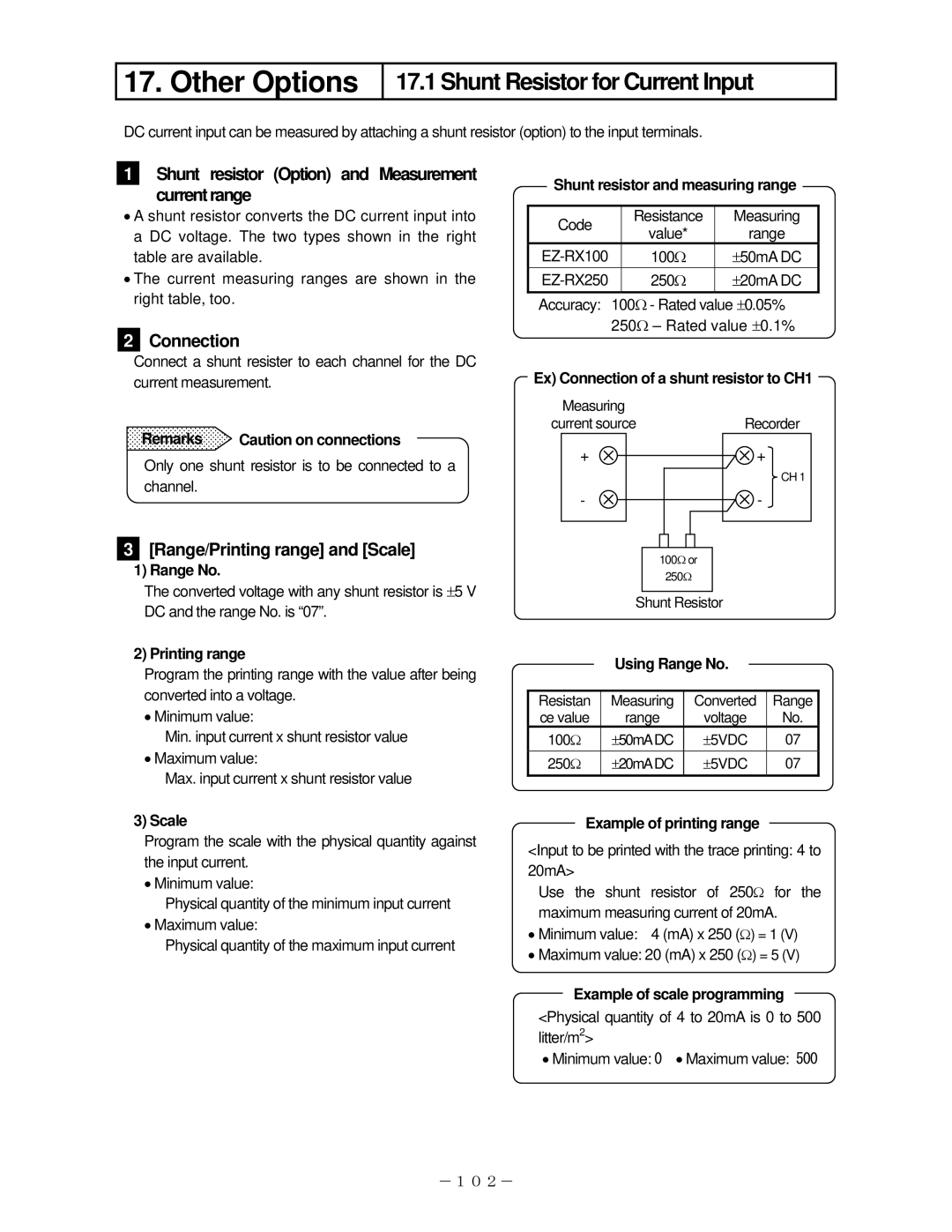
Ex) Connection of a shunt resistor to CH1
Remarks Caution on connections
Only one shunt resistor is to be connected to a channel.
3[Range/Printing range] and [Scale]
1)Range No.
The converted voltage with any shunt resistor is ±5 V DC and the range No. is “07”.
Measuring
current source
+
-
100Ω or
250Ω
Shunt Resistor
Recorder
+
CH 1
-
2) Printing range
Program the printing range with the value after being converted into a voltage.
•Minimum value:
Min. input current x shunt resistor value
•Maximum value:
Max. input current x shunt resistor value
3) Scale
Program the scale with the physical quantity against the input current.
•Minimum value:
Physical quantity of the minimum input current
•Maximum value:
Physical quantity of the maximum input current
Using Range No.
Resistan | Measuring | Converted | Range |
ce value | range | voltage | No. |
100Ω | ±50mADC | ±5VDC | 07 |
250Ω | ±20mADC | ±5VDC | 07 |
Example of printing range
<Input to be printed with the trace printing: 4 to 20mA>
Use the shunt resistor of 250Ω for the maximum measuring current of 20mA.
•Minimum value: 4 (mA) x 250 (Ω) = 1 (V)
•Maximum value: 20 (mA) x 250 (Ω) = 5 (V)
Example of scale programming
<Physical quantity of 4 to 20mA is 0 to 500 litter/m2>
• Minimum value: 0 • Maximum value: 500
-102-