18. ADJUSTMENT
18.1 Adjustment of Measured Values
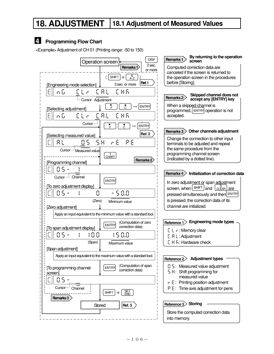
4 Programming Flow Chart
<Example> Adjustment of CH 01 (Printing range:
Operation screen |
| DISP | |
Remarks1 | 2 sec. | ||
| |||
| |||
| or more | ||
|
|
|
|
|
|
|
| ( SHIFT | + | 6 | ) | |
|
|
|
|
|
| |||||
[Engineering mode selection] |
| 3 sec. or more | Ref.1 | |||||||
|
| |||||||||
|
|
|
|
|
|
|
| |||
| |
| ||||||||
|
|
|
|
|
|
|
|
|
| |
|
|
|
|
|
|
|
| |||
|
|
| Cursor | Adjustment |
|
|
|
| ||
|
|
|
|
|
| ° | ° | → ENTRY | ||
[Selecting adjustment] |
| F | C |
|
| |||||
|
|
|
|
| ||||||
|
|
|
|
|
|
|
| |||
| |
| ||||||||
|
|
| Cursor |
|
|
|
| |||
|
|
| ° | ° | → ENTRY | |||||
|
|
|
|
|
|
| F | C |
|
|
[Selecting measured value] |
|
|
|
| Ref. 2 | |||||
|
|
|
|
|
|
|
| |||
| |
| ||||||||
| Cursor |
|
|
|
|
|
|
|
|
|
|
|
|
|
|
|
|
|
| ||
| Measured value | 1 |
|
|
| |||||
|
|
|
|
|
|
|
|
| ||
|
|
|
|
|
| CHART |
|
|
| |
[Programming channel] | Remarks 2 |
|


Cursor Channel
ENTRY
[To zero adjustment display]


(Zero) Minimum value
[Zero adjustment]
Apply an input equivalent to the minimum value with a standard tool.
|
|
| (Computation of zero | |
[To span adjustment display] | ENTRY correction data) | |||
|
|
|
|
|
| | |||
| (Span) |
|
|
|
|
|
|
| |
|
| Maximum value | ||
[Span adjustment]
Apply an input equivalent to the maximum value with a standard tool.
[To programming channel | ENTRY | (Computation of span |
screen] |
| correction data) |
|
|


Cursor Channel
SHIFT + SETEND
Remarks3
| Stored | Ref. 3 | |
|
|
|
|
|
|
|
|
By returning to the operation Remarks 1 screen
Computed correction data are canceled if the screen is returned to the operation screen in the procedures before [Storing].
|
|
Remarks 2 | Skipped channel does not |
accept any [ENTRY] key |
When a skipped channel is programmed, ENTRY operation is not accepted.
Remarks 3 Other channels adjustment
Change the connection to other input terminals to be adjusted and repeat the same procedure from the programming channel screen (indicated by a dotted line).
Remarks 4 Initialization of correction data
In zero adjustment or span adjustment
0
screen, when SHIFT and CLEAR are pressed simultaneously and then ENTRY is pressed, the correction data of its channel are initialized.
Reference 1 Engineering mode types
: Memory clear
: Adjustment
: Hardware check
Reference 2 Adjustment types
: Measured value adjustment
: Shift programming for measured value
: Printing position adjustment
:
Reference 3 Storing
Store the computed correction data into memory.
-106-