11. OTHER PROGRAMMING
11.5 Alarm
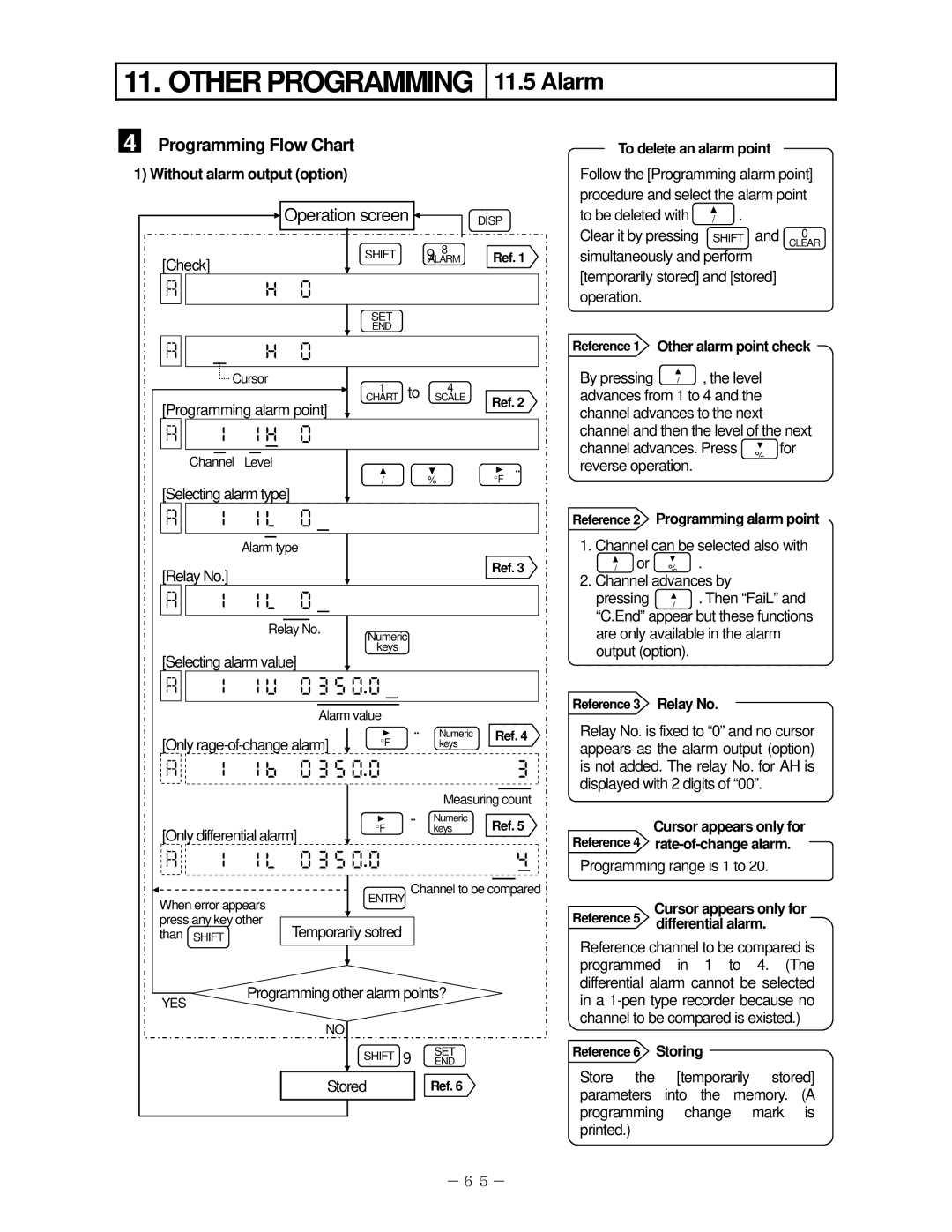
4 Programming Flow Chart
1) Without alarm output (option)
|
|
|
|
|
|
|
|
|
|
| Operation screen |
|
| 8 |
| DISP | ||||||||||||||
|
|
|
|
|
|
|
| |||||||||||||||||||||||
|
|
|
|
|
|
|
|
|
|
|
|
|
| SHIFT | + |
|
|
| Ref. 1 | |||||||||||
|
|
|
|
|
|
|
|
|
|
|
|
|
|
|
|
| ||||||||||||||
[Check] |
|
|
|
|
|
|
|
| ALARM |
| ||||||||||||||||||||
|
|
|
|
|
|
|
|
|
|
|
|
|
|
|
|
|
|
|
|
|
|
|
|
| ||||||
|
|
|
|
|
|
|
| |
|
|
|
|
|
|
|
|
|
|
|
|
|
|
|
|
| |||||
|
|
|
|
|
|
|
|
|
|
|
|
|
| SET |
|
|
|
|
|
|
|
|
|
|
|
|
| |||
|
|
|
|
|
|
|
|
|
|
|
|
|
|
|
|
|
|
|
|
|
|
|
|
|
|
| ||||
|
|
|
|
|
|
|
|
|
|
|
|
|
| END |
|
|
|
|
|
|
|
|
|
|
|
|
| |||
|
|
|
|
|
|
|
|
|
|
|
|
|
|
|
|
|
|
|
|
|
|
|
|
|
|
|
|
|
|
|
|
|
|
|
|
|
|
| |
|
|
|
|
|
|
|
|
|
|
|
|
|
|
|
|
| |||||
|
|
|
|
|
| Cursor | 1 |
|
|
| to |
| 4 |
|
|
|
|
|
|
|
|
| ||||||||
|
|
|
|
|
|
|
|
|
|
|
|
|
|
|
|
|
|
| ||||||||||||
|
|
|
|
|
|
|
|
|
|
|
|
|
|
|
|
|
|
|
|
|
|
|
|
|
|
| ||||
[Programming alarm point] | CHART | SCALE | Ref. 2 | |||||||||||||||||||||||||||
|
|
|
|
|
|
|
|
| ||||||||||||||||||||||
|
|
|
|
|
|
|
|
|
|
|
|
|
|
|
|
| ||||||||||||||
| |
|
|
|
|
|
|
|
|
|
|
|
|
|
|
|
|
| ||||||||||||
|
|
|
|
|
|
|
|
|
|
|
|
|
|
|
|
|
|
|
|
|
|
|
|
|
|
|
|
|
| |
|
|
|
|
|
|
|
|
|
|
|
|
|
|
|
|
|
|
|
|
|
|
|
|
|
|
|
| |||
| Channel | Level |
|
|
|
|
|
|
| → |
|
|
|
|
|
|
|
| ||||||||||||
|
|
|
|
|
|
|
|
|
|
|
|
|
| / |
|
|
|
|
| % | ° |
|
|
|
|
|
| |||
[Selecting alarm type] |
|
|
|
|
|
|
|
| F | |||||||||||||||||||||
|
|
|
|
|
|
|
|
|
|
|
|
|
|
|
|
| ||||||||||||||
| |
|
|
|
|
|
|
|
|
|
|
|
|
|
|
|
|
| ||||||||||||
|
|
|
|
|
|
|
|
|
|
|
|
|
|
|
|
|
|
|
|
|
|
|
|
|
|
|
|
|
|
|
|
|
|
|
|
|
|
|
|
|
|
|
|
|
|
|
|
|
|
|
|
|
|
|
|
|
| ||||
|
|
|
|
|
| Alarm type |
|
|
|
|
|
|
|
|
|
|
|
|
|
|
|
|
| |||||||
[Relay No.] |
|
|
|
|
|
|
|
|
|
|
|
|
|
|
|
|
| Ref. 3 | ||||||||||||
|
|
|
|
|
|
|
|
|
|
|
|
|
|
|
|
|
|
|
|
|
|
|
|
| ||||||
| |
|
|
|
|
|
|
|
|
|
|
|
|
|
|
|
|
| ||||||||||||
|
|
|
|
|
|
|
|
|
|
|
|
|
|
|
|
|
|
|
|
|
|
|
|
|
|
|
|
|
|
|
|
|
|
|
|
|
|
|
|
|
|
|
|
|
|
|
|
|
|
|
|
|
|
|
|
|
|
|
|
|
|
|
|
|
|
|
|
|
|
| Relay No. | Numeric |
|
|
|
|
|
|
|
|
|
|
| |||||||||
|
|
|
|
|
|
|
|
|
|
|
|
|
|
|
|
|
|
|
|
|
|
|
|
| ||||||
[Selecting alarm value] | keys |
|
|
|
|
|
|
|
|
|
|
|
|
| ||||||||||||||||
|
|
|
|
|
|
|
|
|
|
|
|
|
|
|
|
| ||||||||||||||
| |
|
|
|
|
|
|
|
|
|
|
|
|
| ||||||||||||||||
|
|
|
|
|
|
|
|
|
|
|
|
|
|
|
|
|
|
|
|
|
|
|
|
|
|
|
|
|
|
|
|
|
|
|
|
|
|
|
|
|
|
|
|
|
|
|
|
|
|
|
|
|
|
|
|
|
|
| |||
|
|
|
|
|
|
|
|
|
|
|
|
| Alarm value |
|
|
|
|
|
|
|
|
|
|
|
|
| ||||
[Only | → | Numeric |
| Ref. 4 | ||||||||||||||||||||||||||
|
|
| keys |
|
|
|
|
|
|
|
| |||||||||||||||||||
| |
|
|
|
|
|
|
| | |||||||||||||||||||||
|
|
|
|
|
|
|
|
|
|
|
|
|
|
|
|
|
|
|
|
|
|
|
|
|
|
|
| |||
|
|
|
|
|
|
|
|
|
|
|
|
|
|
|
|
|
|
|
|
| Measuring count | |||||||||
[Only differential alarm] | °F | → keysNumeric | Ref. 5 | |||||||||||||||||||||||||||
|
|
|
|
|
|
|
|
|
|
|
|
|
|
|
|
| ||||||||||||||
| |
|
|
|
|
|
|
| | |||||||||||||||||||||
|
|
|
|
|
|
|
|
|
|
|
|
|
|
|
|
|
|
| ||||||||||||
When error appears | ENTRY Channel to be compared | |||||||||||||||||||||||||||||
|
|
|
|
|
|
|
|
|
|
|
|
|
|
|
|
| ||||||||||||||
press any key other |
|
|
|
|
|
|
|
|
|
|
|
|
|
|
|
|
|
| ||||||||||||
|
|
|
|
|
|
|
|
|
|
|
|
|
|
|
|
|
| |||||||||||||
than SHIFT |
|
|
|
|
| Temporarily sotred |
|
|
|
|
|
|
|
|
|
|
|
|
| |||||||||||
To delete an alarm point
Follow the [Programming alarm point] procedure and select the alarm point
to be deleted with | / . |
|
Clear it by pressing | SHIFT and | 0 |
CLEAR |
simultaneously and perform [temporarily stored] and [stored] operation.
Reference 1 Other alarm point check
By pressing / , the level advances from 1 to 4 and the channel advances to the next channel and then the level of the next
channel advances. Press | % for |
reverse operation. |
|
Reference 2 |
| Programming alarm point | ||
1. Channel can be selected also with | ||||
/ or | % . |
| ||
2. Channel advances by | ||||
pressing | / | . Then “FaiL” and | ||
“C.End” appear but these functions | ||||
are only available in the alarm | ||||
output (option). |
|
| ||
|
| |||
Reference 3 |
| Relay No. |
| |
|
|
|
|
|
Relay No. is fixed to “0” and no cursor appears as the alarm output (option) is not added. The relay No. for AH is displayed with 2 digits of “00”.
Reference 4 | Cursor appears only for |
|
|
Programming range is 1 to 20. | |
|
|
Reference 5 | Cursor appears only for |
differential alarm. | |
YES
Programming other alarm points?
NO
SHIFT + SETEND
Stored | Ref. 6 | |
|
|
|
|
|
|
Reference channel to be compared is programmed in 1 to 4. (The differential alarm cannot be selected in a
Reference 6 Storing
Store the [temporarily stored] parameters into the memory. (A programming change mark is printed.)
-65-