12. ALARM OUTPUT
12.3 Output Wiring (AND/OR) Setting
This explanation is only for the alarm output (option). Press°C simultaneously for 3 seconds or more to display the “Output Wiring (AND or OR)” programming screen. Program it for each relay No. The default is “OR” for all relay Nos.
1
AND/OR
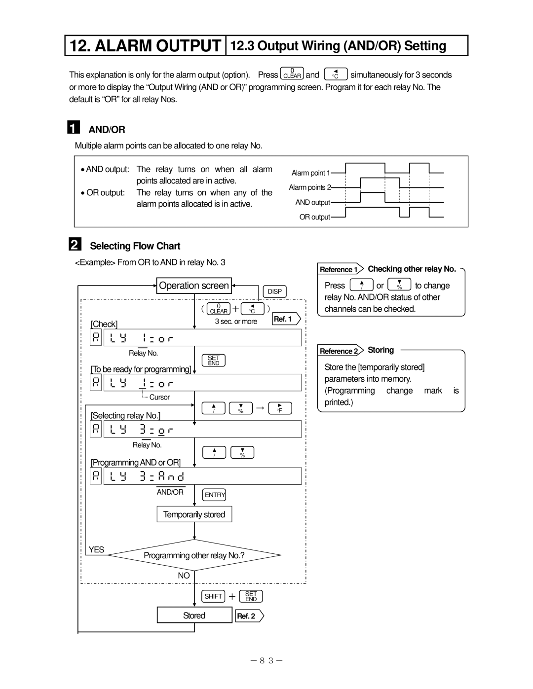
Multiple alarm points can be allocated to one relay No.
•AND output: The relay turns on when all alarm points allocated are in active.
•OR output: The relay turns on when any of the alarm points allocated is in active.
Alarm point 1![]() Alarm points 2
Alarm points 2![]()
AND output![]() OR output
OR output![]()
2 Selecting Flow Chart
<Example> From OR to AND in relay No. 3
| Operation screen |
|
| DISP | ||
|
|
|
|
|
| |
|
| ( | 0 | + | °C | ) |
|
| CLEAR | ||||
[Check] |
|
| 3 sec. or more | Ref. 1 | ||
|
|
| ||||
|
|
|
|
|
| |
| Relay No. |
| SET |
|
|
|
|
|
|
|
|
| |
[To be ready for programming] |
| END |
|
|
| |
|
|
|
|
| ||
|
|
|
|
|
| |
| Cursor |
|
|
|
|
|
[Selecting relay No.] |
| / | % | → | °F | |
|
| |||||
|
|
|
|
| ||
|
|
|
|
|
| |
| Relay No. |
|
|
|
|
|
[ProgrammingAND or OR] |
| / | % |
|
| |
|
|
|
|
| ||
|
|
|
|
|
| |
| AND/OR | ENTRY |
|
|
| |
|
|
|
|
| ||
| Temporarily stored |
|
|
| ||
YES | Programming other relay No.? |
|
| |||
|
|
| ||||
| NO |
|
|
|
|
|
|
| SHIFT + | SET |
| ||
|
| END |
| |||
|
|
|
|
|
| |
| Stored |
| Ref. 2 |
| ||
|
|
|
|
| -83- | |
Reference 1 Checking other relay No.
Press | / | or % to change | ||
relay No. AND/OR status of other | ||||
channels can be checked. | ||||
|
|
|
| |
Reference 2 |
|
| Storing |
|
Store the [temporarily stored] parameters into memory. (Programming change mark is printed.)