4.CONNECTIONS
4.3 Power Terminals
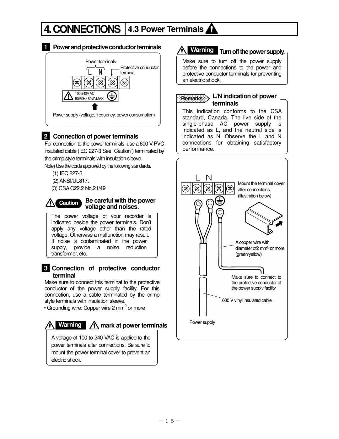
1Power and protective conductor terminals
Power terminals
Protective conductor
L N terminal
![]() 50/60Hz 60VAMAX
50/60Hz 60VAMAX
Power supply (voltage, frequency, power consumption)
2Connection of power terminals
For connection to the power terminals, use a 600 V PVC insulated cable (IEC
Note) Use the cords approved by the following standards.
(1)IEC
(2)ANSI/UL817,
(3)CSA C22.2 No.21/49
Caution Be careful with the power voltage and noises.
The power voltage of your recorder is indicated beside the power terminals. Don’t apply any voltage other than the rated voltage. Otherwise a malfunction may result. If noise is contaminated in the power supply, provide a noise reduction transformer, etc.
![]() Warning Turn off the power supply.
Warning Turn off the power supply.
Make sure to turn off the power supply before the connections to the power and protective conductor terminals for preventing an electric shock.
Remarks L/N indication of power terminals
This indication conforms to the CSA standard, Canada. The live side of the
L N
Mount the terminal cover after connections. (Illustration below)
A copper wire with diameter of2 mm2 or more (green/yellow)
3 Connection of protective conductor terminal
Make sure to connect this terminal to the protective conductor of the power supply facility. For this connection, use a cable terminated by the crimp style terminals with insulation sleeve.
• Grounding wire: Copper wire 2 mm2 or more
Warning | mark at power terminals | Power supply |
|
A voltage of 100 to 240 VAC is applied to the power terminals after connections. Be sure to mount the power terminal cover to prevent an electric shock.
Make sure to connect to the protective conductor of the power supply facility.
600 V vinyl insulated cable
-15-