4.CONNECTIONS
4.5 Alarm Output Terminals
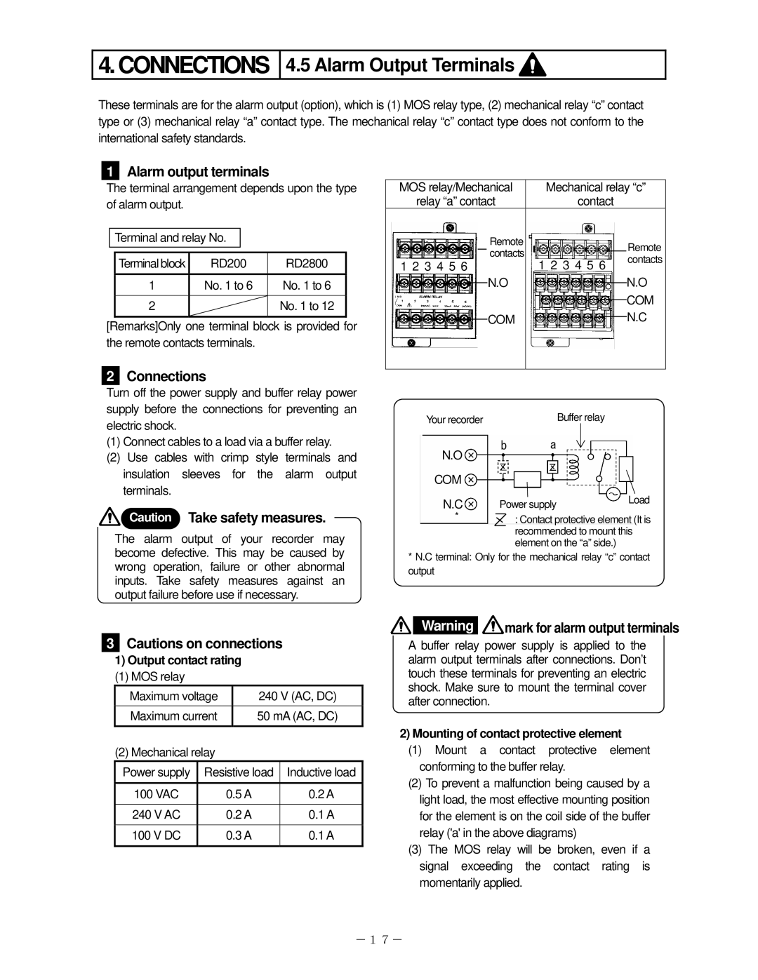
These terminals are for the alarm output (option), which is (1) MOS relay type, (2) mechanical relay “c” contact type or (3) mechanical relay “a” contact type. The mechanical relay “c” contact type does not conform to the international safety standards.
1Alarm output terminals
The terminal arrangement depends upon the type of alarm output.
Terminal and relay No.
Terminal block | RD200 | RD2800 |
1 | No. 1 to 6 | No. 1 to 6 |
|
|
|
2 |
| No. 1 to 12 |
|
|
|
[Remarks]Only one terminal block is provided for the remote contacts terminals.
2Connections
MOS relay/Mechanical
relay “a” contact
Remote contacts
1 2 3 4 5 6
N.O
COM
Mechanical relay “c”
contact
Remote 1 2 3 4 5 6 contacts
N.O
COM
N.C
Turn off the power supply and buffer relay power supply before the connections for preventing an electric shock.
(1)Connect cables to a load via a buffer relay.
(2)Use cables with crimp style terminals and insulation sleeves for the alarm output terminals.
![]() Caution Take safety measures.
Caution Take safety measures.
The alarm output of your recorder may
Your recorder
N.O
COM
N.C
*
Buffer relay
b a
Power supply | Load |
|
:Contact protective element (It is recommended to mount this element on the “a” side.)
become defective. This may be caused by wrong operation, failure or other abnormal inputs. Take safety measures against an output failure before use if necessary.
*N.C terminal: Only for the mechanical relay “c” contact output
3 | Cautions on connections |
| Warning | mark for alarm output terminals | ||
| A buffer relay power supply is applied to the | |||||
| 1) Output contact rating |
| alarm output terminals after connections. Don’t | |||
| (1) MOS relay |
|
|
| touch these terminals for preventing an electric | |
| Maximum voltage | 240 V (AC, DC) | shock. Make sure to mount the terminal cover | |||
| after connection. |
| ||||
| Maximum current | 50 mA (AC, DC) |
| |||
|
|
| ||||
|
|
|
|
| 2) Mounting of contact protective element | |
| (2) Mechanical relay |
|
| (1) Mount a contact protective element | ||
| Power supply | Resistive load | Inductive load | conforming to the buffer relay. | ||
| (2) To prevent a malfunction being caused by a | |||||
| 100 VAC |
| 0.5 A | 0.2 A | ||
|
| light load, the most effective mounting position | ||||
| 240 V AC |
| 0.2 A | 0.1 A | ||
|
| for the element is on the coil side of the buffer | ||||
| 100 V DC |
| 0.3 A | 0.1 A | relay ('a' in the above diagrams) | |
|
|
|
|
| (3) The MOS relay will be broken, even if a | |
|
|
|
|
| signal exceeding the contact rating is | |
|
|
|
|
| momentarily applied. | |
-17-