18. ADJUSTMENT
18.3 Adjustment of Printing Position
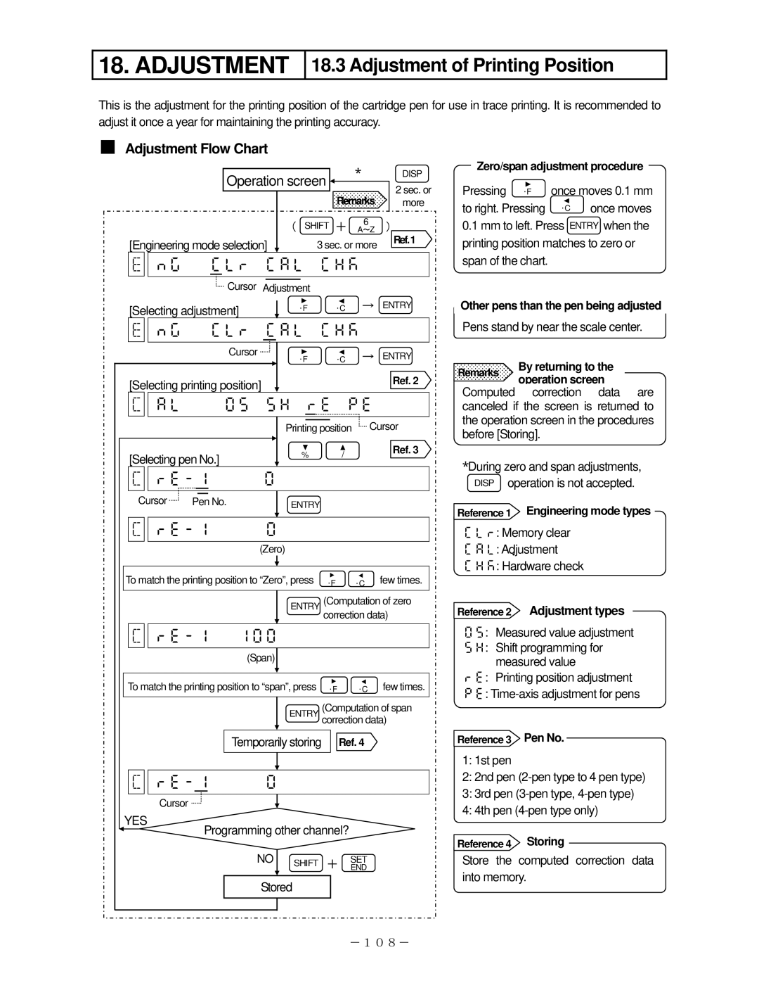
This is the adjustment for the printing position of the cartridge pen for use in trace printing. It is recommended to adjust it once a year for maintaining the printing accuracy.
■Adjustment Flow Chart
|
|
|
| ∗ |
| DISP |
| Operation screen |
|
| |||
| Remarks |
| 2 sec. or | |||
| ||||||
|
|
|
| |||
|
|
|
| more | ||
| ( | SHIFT + | 6 | ) | ||
| A~Z | |||||
[Engineering mode selection] | 3 sec. or more |
| Ref.1 | |||
|
| |||||
![]() Cursor Adjustment
Cursor Adjustment
[Selecting adjustment] | ° | ° | → ENTRY | |||
F | C |
|
| |||
| |
| ||||
|
| Cursor | ° | ° | → ENTRY | |
|
|
| F | C |
|
|
[Selecting printing position] |
|
| Ref. 2 | |||
|
| | ||||
|
|
| Printing position | Cursor | ||
[Selecting pen No.] |
| % | / |
| Ref. 3 | |
|
|
| ||||
|
|
|
|
| ||
|
| |
|
|
| |
Cursor | Pen No. | ENTRY |
|
|
| |
|
| |
|
|
| |
|
|
| (Zero) |
|
|
|
To match the printing position to “Zero”, press | ° | ° | few times. | |||
|
|
|
| F | C |
|
|
|
| ENTRY | (Computation of zero | ||
|
|
|
| correction data) | ||
| |
|
|
| ||
|
| (Span) |
|
|
| |
To match the printing position to “span”, press | °F | °C | few times. | |||
|
|
| ENTRY | (Computation of span | ||
|
|
|
| correction data) | ||
|
| Temporarily storing | Ref. 4 |
| ||
|
| |
|
|
| |
Cursor |
|
|
|
|
|
|
YES | Programming other channel? |
| ||||
|
| |||||
|
| NO SHIFT | + | SET |
| |
|
|
|
|
| END |
|
|
|
| Stored |
|
|
|
|
|
|
|
| -108- | |
Zero/span adjustment procedure
Pressing °F once moves 0.1 mm to right. Pressing °C once moves
0.1mm to left. Press ENTRY when the printing position matches to zero or span of the chart.
Other pens than the pen being adjusted
Pens stand by near the scale center.
Remarks By returning to the operation screen
Computed correction data are canceled if the screen is returned to the operation screen in the procedures before [Storing].
∗During zero and span adjustments, DISP operation is not accepted.
Reference 1 Engineering mode types
: Memory clear
: Adjustment
: Hardware check
Reference 2 Adjustment types
: Measured value adjustment
: Shift programming for measured value
: Printing position adjustment
:
Reference 3 Pen No.
1:1st pen
2:2nd pen
3:3rd pen
4:4th pen
Reference 4 Storing
Store the computed correction data into memory.
