12. ALARM OUTPUT
12.1 Alarm Output Programming Items
This explanation is only for the alarm output (option). The alarm output programming is necessary after programming the “alarm”.
1
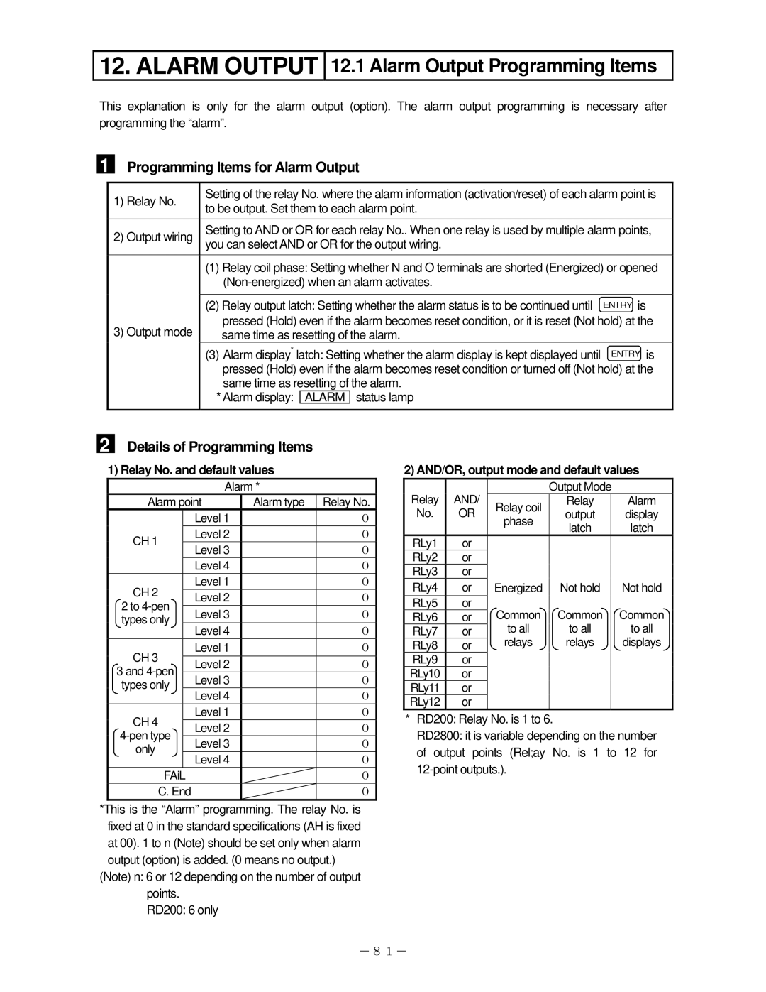
Programming Items for Alarm Output
1) Relay No. | Setting of the relay No. where the alarm information (activation/reset) of each alarm point is | |||
to be output. Set them to each alarm point. |
| |||
|
| |||
|
|
|
| |
2) Output wiring | Setting to AND or OR for each relay No.. When one relay is used by multiple alarm points, | |||
| you can select AND or OR for the output wiring. |
| ||
| (1) Relay coil phase: Setting whether N and O terminals are shorted (Energized) or opened | |||
|
| |||
|
|
|
|
|
| (2) Relay output latch: Setting whether the alarm status is to be continued until | ENTRY is | ||
3) Output mode | pressed (Hold) even if the alarm becomes reset condition, or it is reset (Not hold) at the | |||
same time as resetting of the alarm. |
| |||
| (3) Alarm display* latch: Setting whether the alarm display is kept displayed until | ENTRY is | ||
| pressed (Hold) even if the alarm becomes reset condition or turned off (Not hold) at the | |||
| same time as resetting of the alarm. |
| ||
| * Alarm display: | ALARM | status lamp |
|
|
|
|
|
|
2 Details of Programming Items
1) Relay No. and default values
Alarm *
Alarm point | Alarm type | Relay No. | ||
|
| Level 1 |
| 0 |
CH 1 |
| Level 2 |
| 0 |
| Level 3 |
| 0 | |
|
|
| ||
|
| Level 4 |
| 0 |
CH 2 |
| Level 1 |
| 0 |
| Level 2 |
| 0 | |
2 to |
|
| ||
| Level 3 |
| 0 | |
types only |
|
| ||
| Level 4 |
| 0 | |
|
|
| ||
CH 3 |
| Level 1 |
| 0 |
| Level 2 |
| 0 | |
3 and |
|
| ||
| Level 3 |
| 0 | |
types only |
|
| ||
| Level 4 |
| 0 | |
|
|
| ||
CH 4 |
| Level 1 |
| 0 |
| Level 2 |
| 0 | |
|
| |||
| Level 3 |
| 0 | |
only |
|
| ||
| Level 4 |
| 0 | |
|
|
| ||
FAiL |
|
|
| 0 |
C. End |
|
| 0 | |
*This is the “Alarm” programming. The relay No. is fixed at 0 in the standard specifications (AH is fixed at 00). 1 to n (Note) should be set only when alarm output (option) is added. (0 means no output.)
(Note) n: 6 or 12 depending on the number of output points.
RD200: 6 only
2) AND/OR, output mode and default values
Relay | AND/ |
| Output Mode |
| |
Relay coil | Relay |
| Alarm | ||
No. | OR | output |
| display | |
phase |
| ||||
|
| latch |
| latch | |
|
|
|
| ||
RLy1 | or |
|
|
|
|
RLy2 | or |
|
|
|
|
RLy3 | or |
|
|
|
|
RLy4 | or | Energized | Not hold |
| Not hold |
RLy5 | or | Common | Common |
| Common |
RLy6 | or |
| |||
RLy7 | or | to all | to all |
| to all |
RLy8 | or | relays | relays |
| displays |
RLy9 | or |
|
|
|
|
RLy10 | or |
|
|
|
|
RLy11 | or |
|
|
|
|
RLy12 | or |
|
|
|
|
*RD200: Relay No. is 1 to 6.
RD2800: it is variable depending on the number of output points (Rel;ay No. is 1 to 12 for
-81-