4.CONNECTIONS 4.2 Cautions on Connections
Observe the following cautions during connections for securing safety and reliability.
1Power supply
Use a
Warning | A switch and an overcurrent | |
protective device | ||
|
Prepare a switch and an overcurrent protective device (3 A) to the power supply for preventing an accidental electric shock during connection work. This instrument is not provided with any replaceable overcurrent protective device.
Warning | Turn off the power supply | |
before starting connections. | ||
|
Make sure to turn off the power supply before connecting the power and the input/output terminals to prevent an electric shock.
2Keep the input/output connections away from high voltage power circuits
Don’t place the input/output cables close to or in parallel with any strong power circuits including power lines. Place the cables 50cm or more away from high voltage power circuits when they are placed close to or in parallel to other circuits.
3Keep the thermocouple input away
from a heat source
For thermocouple inputs, keep the input terminals away from a heat source (a heating body) to reduce a reference junction compensation error. Don’t expose the input terminals to direct sunlight, etc.
4Keep the input/output connections
away from noise source
Keep all connection cables away from noise source as far as possible, otherwise a malfunction may occur. Provide a solution if the cables cannot be separated from a noise source due to unavoidable circumstances.
Major noise sources | Remedial measures | |
|
| |
Electromagnetic switch, | Insert noise filters | |
between power | ||
etc. Power line having | ||
terminals and | ||
waveform distortion, | ||
input/output terminals. | ||
Inverter, Thyristor regulator | ||
A CR filter is often used. | ||
|
5Use crimp style terminals
(1)Mount crimp style terminals for connection cable terminations to prevent any looseness or disconnection of terminals or a
(2)Use the crimp style terminals with an insulation sleeve to prevent an electric shocks.
6Unused terminals
Don’t use any unused terminals for relaying, otherwise the electric circuits may be damaged.
Warning | Secure the connected |
| cables properly. |
Secure the connected cables so as not to allow them to be hooked by a person or a substance, otherwise the connections may be cut and disrupted, and may cause an electric shock or other accidents.
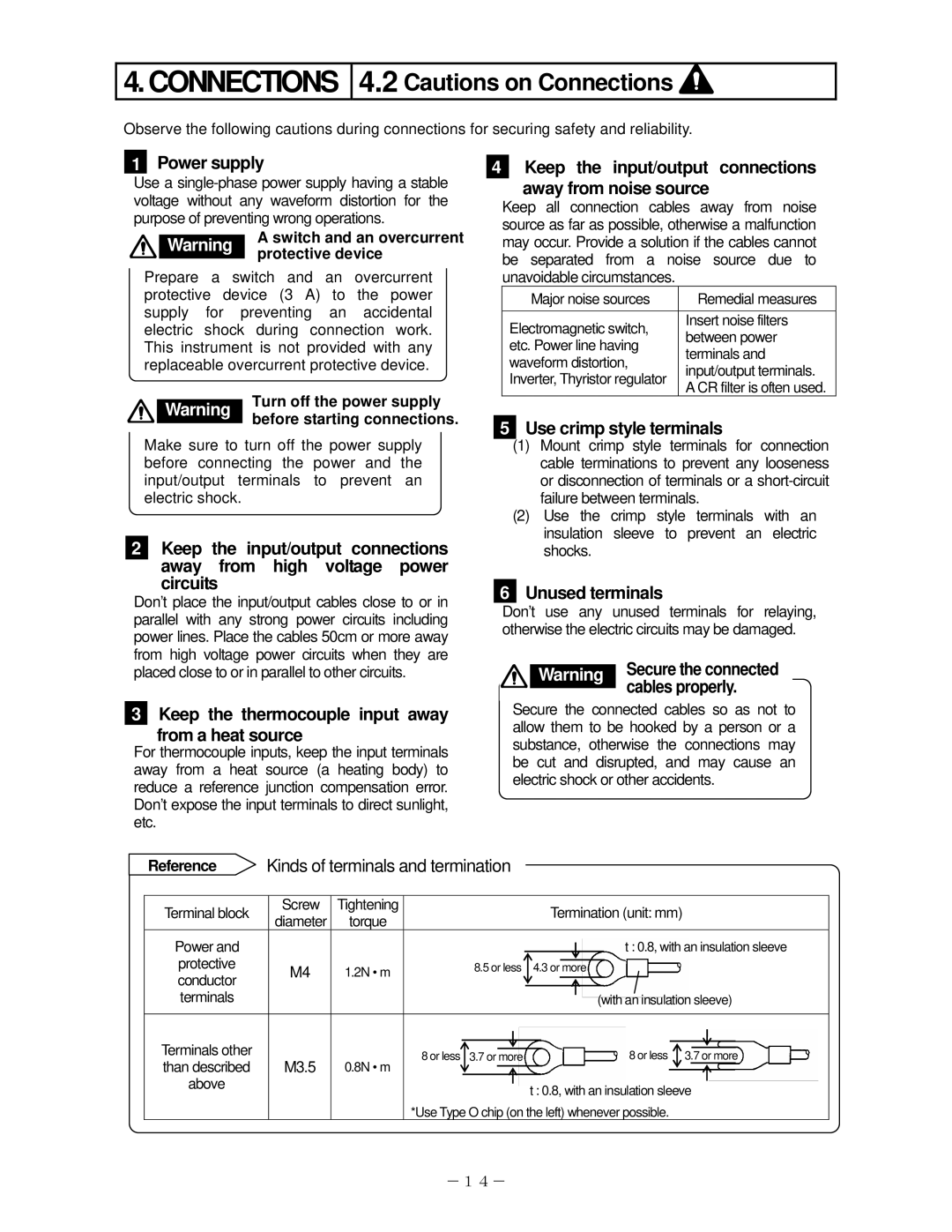
Reference | Kinds of terminals and termination |
|
|
|
|
|
|
|
|
|
|
| |||||||
|
|
|
|
|
|
|
|
|
|
|
|
|
|
|
|
|
|
|
|
|
|
|
|
|
|
|
|
|
|
|
|
|
|
|
|
|
|
|
|
Terminal block |
| Screw | Tightening |
|
|
|
|
|
| Termination (unit: mm) | |||||||||
| diameter | torque |
|
|
|
|
|
| |||||||||||
|
|
|
|
|
|
|
|
|
|
|
|
|
|
|
|
|
| ||
Power and |
|
|
|
|
|
|
|
|
|
|
|
|
| t : 0.8, with an insulation sleeve | |||||
protective |
|
|
|
| 8.5 or less |
|
|
|
|
|
|
|
|
|
|
| |||
| M4 | 1.2N • m |
| 4.3 or more | |||||||||||||||
conductor |
|
| |||||||||||||||||
|
|
|
|
|
|
|
|
|
|
|
|
|
|
|
|
|
|
| |
terminals |
|
|
|
|
|
|
|
|
|
|
| (with an insulation sleeve) | |||||||
|
|
|
|
|
|
|
|
|
|
|
|
|
|
|
|
|
|
|
|
Terminals other |
|
|
|
|
|
|
|
|
|
|
|
|
|
|
|
|
|
|
|
|
|
|
|
|
|
|
|
|
|
|
|
|
|
|
|
|
|
| |
|
|
|
|
|
|
|
|
|
|
|
|
|
|
|
|
|
|
| |
| M3.5 |
| 8 or less | 3.7 or more |
|
|
|
|
|
|
|
| 8 or less 3.7 or more |
| |||||
than described |
| 0.8N • m |
|
|
|
|
|
|
|
| |||||||||
|
|
|
|
|
|
|
|
|
|
|
|
|
|
|
|
| |||
|
|
|
|
|
|
|
|
|
|
|
|
|
|
|
|
| |||
above |
|
|
|
|
|
|
|
|
|
|
|
|
|
|
|
|
|
|
|
|
|
|
|
|
|
|
| t : 0.8, with an insulation sleeve | |||||||||||
|
|
|
|
|
|
|
|
| |||||||||||
|
|
|
| *Use Type O chip (on the left) whenever possible. | |||||||||||||||
-14-