18. ADJUSTMENT
18.1 Adjustment of Measured Values
3
Connections
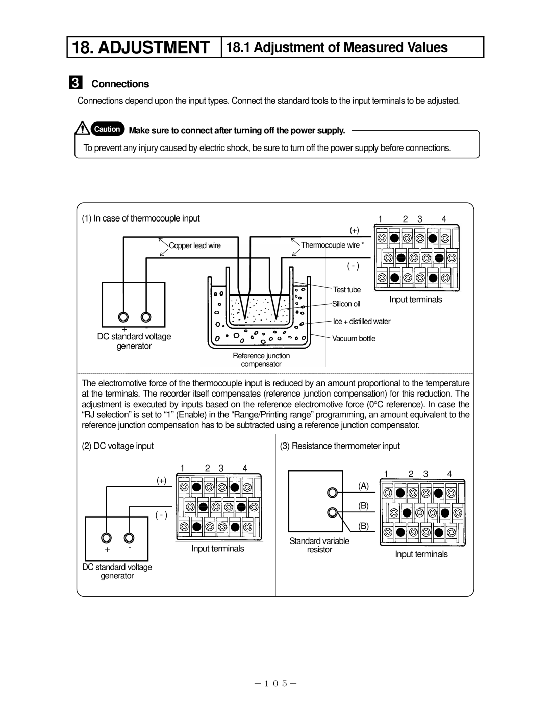
Connections depend upon the input types. Connect the standard tools to the input terminals to be adjusted.
![]() Caution Make sure to connect after turning off the power supply.
Caution Make sure to connect after turning off the power supply.
To prevent any injury caused by electric shock, be sure to turn off the power supply before connections.
(1) In case of thermocouple input | 1 | 2 3 | 4 | |||||
|
|
|
| (+) |
|
|
| |
|
|
| Copper lead wire | Thermocouple wire * |
|
|
| |
|
|
|
| ( - ) |
|
|
| |
|
|
|
|
|
|
| ||
|
|
|
|
| Test tube |
|
|
|
|
|
|
|
|
|
|
| |
|
|
|
|
|
| Input terminals | ||
|
|
|
|
| Silicon oil | |||
|
|
|
|
|
|
| ||
| + | - |
|
| Ice + distilled water |
| ||
|
|
|
|
|
|
| ||
DC standard voltage |
| Vacuum bottle |
|
| ||||
| generator |
|
|
|
|
| ||
Reference junction
compensator
The electromotive force of the thermocouple input is reduced by an amount proportional to the temperature at the terminals. The recorder itself compensates (reference junction compensation) for this reduction. The adjustment is executed by inputs based on the reference electromotive force (0°C reference). In case the “RJ selection” is set to “1” (Enable) in the “Range/Printing range” programming, an amount equivalent to the reference junction compensation has to be subtracted using a reference junction compensator.
(2) DC voltage input
1 2 3 4
(+)
( - )
+ | - | Input terminals |
DC standard voltage
generator
(3)Resistance thermometer input
12 3 4
(A)
(B)
(B)
Standard variable |
|
resistor | Input terminals |
|
-105-