12. ALARM OUTPUT
12.2 Programming of Relay No.
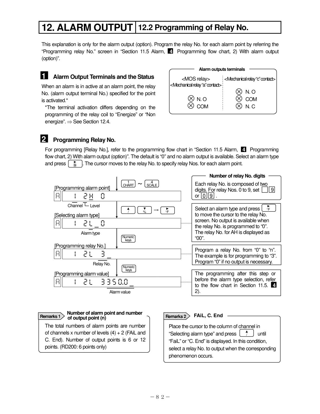
This explanation is only for the alarm output (option). Program the relay No. for each alarm point by referring the “Programming relay No.” screen in “Section 11.5 Alarm, 4 Programming flow chart, 2) With alarm output (option)”.
1 Alarm Output Terminals and the Status
When an alarm is in active at an alarm point, the relay No. (alarm output terminal No.) specified for the point is activated.*
*The terminal activation differs depending on the programming of the relay coil to “Energize” or “Non energize”. ⇒ See Section 12.4.
Alarm outputs terminals
<MOS relay> | <Mechanicalrelay“c”contact> |
<Mechanicalrelay“a”contact>
| N. O |
N. O | COM |
COM | N. C |
2
Programming Relay No.
For programming [Relay No.], refer to the programming flow chart in “Section 11.5 Alarm,
4
Programming
flow chart, 2) With alarm output (option)”. The default is “0” and no alarm output is available. Select an alarm type and press ![]() . The cursor moves to the relay No. to specify relay Nos. for each alarm point.
. The cursor moves to the relay No. to specify relay Nos. for each alarm point.
| 1 | ~ | 4 |
[Programming alarm point] | CHART | SCALE | |
|
|
|


Channel ![]() Level
Level
Number of relay No. digits
Each relay No. is composed of two
digits. For relay Nos. 0 to 9, set ![]()
![]()
![]() 9 or 0 9 .
9 or 0 9 .
[Selecting alarm type]
/ % → °F
Select an alarm type and press °F to move the cursor to the relay No.


|
|
| Alarm type |
| Numeric |
|
| ||||||
|
|
|
|
|
|
|
|
|
| ||||
|
|
|
|
|
|
|
| keys |
|
| |||
| [Programming relay No.] |
|
|
|
|
|
|
| |||||
| |
| |
|
|
|
|
|
|
| |||
|
|
|
|
|
|
|
|
|
|
|
|
| |
|
|
|
|
|
|
|
|
|
|
|
|
|
|
|
|
|
|
|
|
|
|
|
|
|
|
| |
|
|
| Relay No. | Numeric |
|
| |||||||
|
|
|
|
|
|
|
|
|
| ||||
| [Programming alarm value] |
| keys |
|
| ||||||||
|
|
|
|
|
|
|
| ||||||
| |
| |
|
| ||||||||
|
|
|
|
|
|
|
|
|
|
|
|
| |
|
|
|
|
|
|
|
|
|
|
|
|
|
|
|
|
|
|
|
|
|
|
|
|
| |||
|
|
|
|
|
|
| Alarm value |
|
| ||||
|
|
|
|
|
| ||||||||
Remarks 1 | Number of alarm point and number | Remarks 2 | |||||||||||
of output point (n) |
|
|
|
|
| ||||||||
screen. No output is available when the relay No. is programmed to “0”. The relay No. for AH is displayed as “00”.
Program a relay No. from “0” to “n”. The example is for programming to “3”. Program “0” if no output is necessary.
The programming after this step or before the alarm type selection, refer to the flow chart in Section 11.5. 4 2).
FAiL, C. End
The total numbers of alarm points are number of channels x number of levels (4) + 2 (FAiL and C. End). Number of output points is 6 or 12 points. (RD200: 6 points only)
Place the cursor to the column of channel in
“Selecting alarm type” and press | / | until |
“FaiL” or “C. End” is displayed. In this condition, select a relay No. to output when the corresponding phenomenon occurs.
-82-