Hardware setup
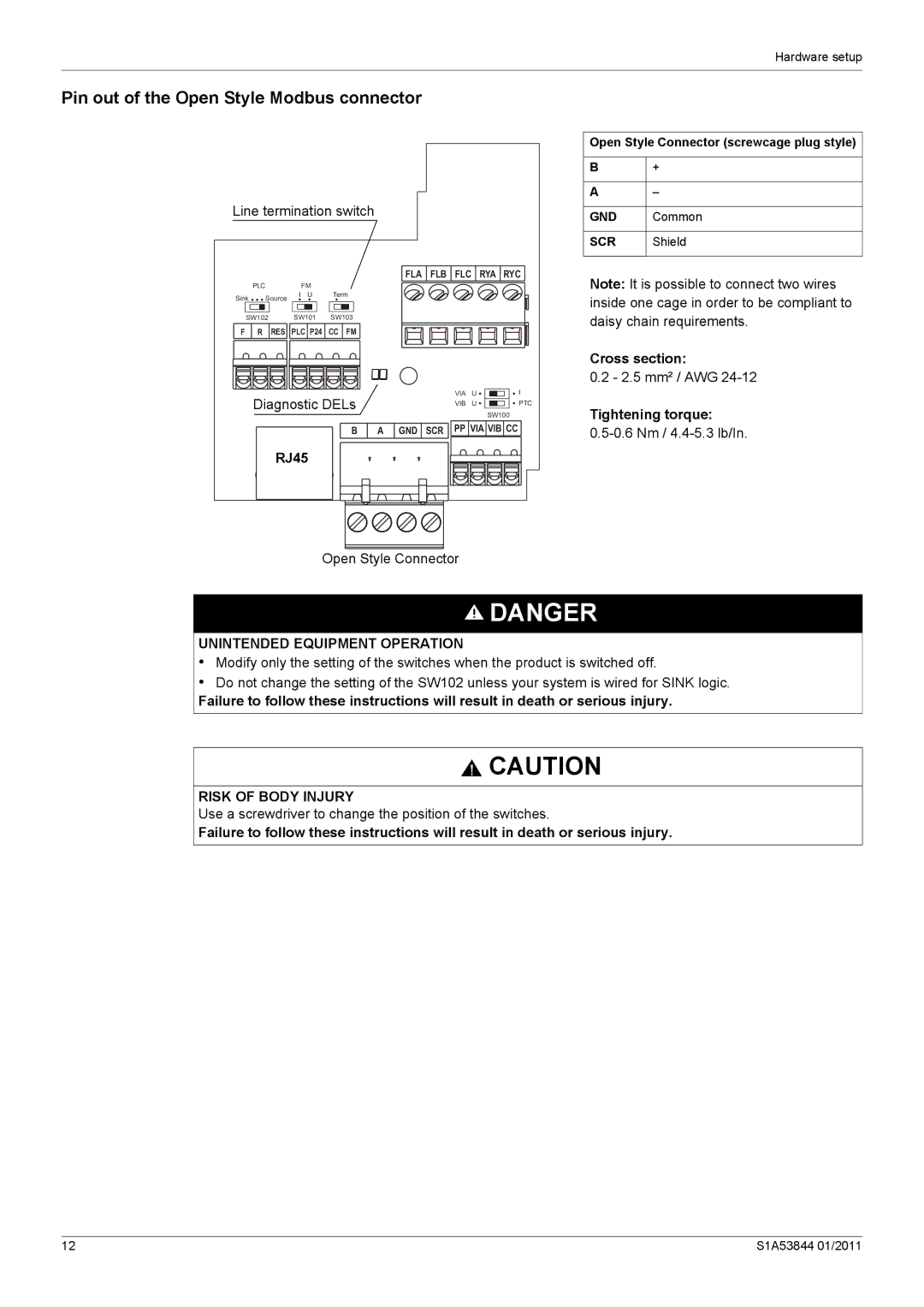
Pin out of the Open Style Modbus connector
Line termination switch |
|
|
|
|
|
| ||||
|
|
|
|
|
| FLA | FLB | FLC |
| RYA RYC |
| PLC |
| FM |
|
|
|
|
|
|
|
Sink | Source | I U | Term |
|
|
|
|
|
| |
|
|
|
|
|
|
|
| |||
SW102 |
| SW101 | SW103 |
|
|
|
|
|
| |
F | R | RES | PLC P24 | CC FM |
|
|
|
|
|
|
| Diagnostic DELs |
|
|
| VIA | U | I | |||
|
|
|
| VIB | U | PTC | ||||
|
|
|
|
|
| SW100 | ||||
|
|
|
|
|
|
|
|
|
| |
|
|
|
| B | A | GND | SCR | PP VIA VIB CC | ||
|
| RJ45 |
|
|
|
|
|
|
| |
Open Style Connector
Open Style Connector (screwcage plug style)
B+
A–
GND | Common |
|
|
SCR | Shield |
Note: It is possible to connect two wires inside one cage in order to be compliant to daisy chain requirements.
Cross section:
0.2 - 2.5 mm² / AWG
Tightening torque:
![]() DANGER
DANGER
UNINTENDED EQUIPMENT OPERATION
•Modify only the setting of the switches when the product is switched off.
•Do not change the setting of the SW102 unless your system is wired for SINK logic.
Failure to follow these instructions will result in death or serious injury.
![]() CAUTION
CAUTION
RISK OF BODY INJURY
Use a screwdriver to change the position of the switches.
Failure to follow these instructions will result in death or serious injury.
12 | S1A53844 01/2011 |
