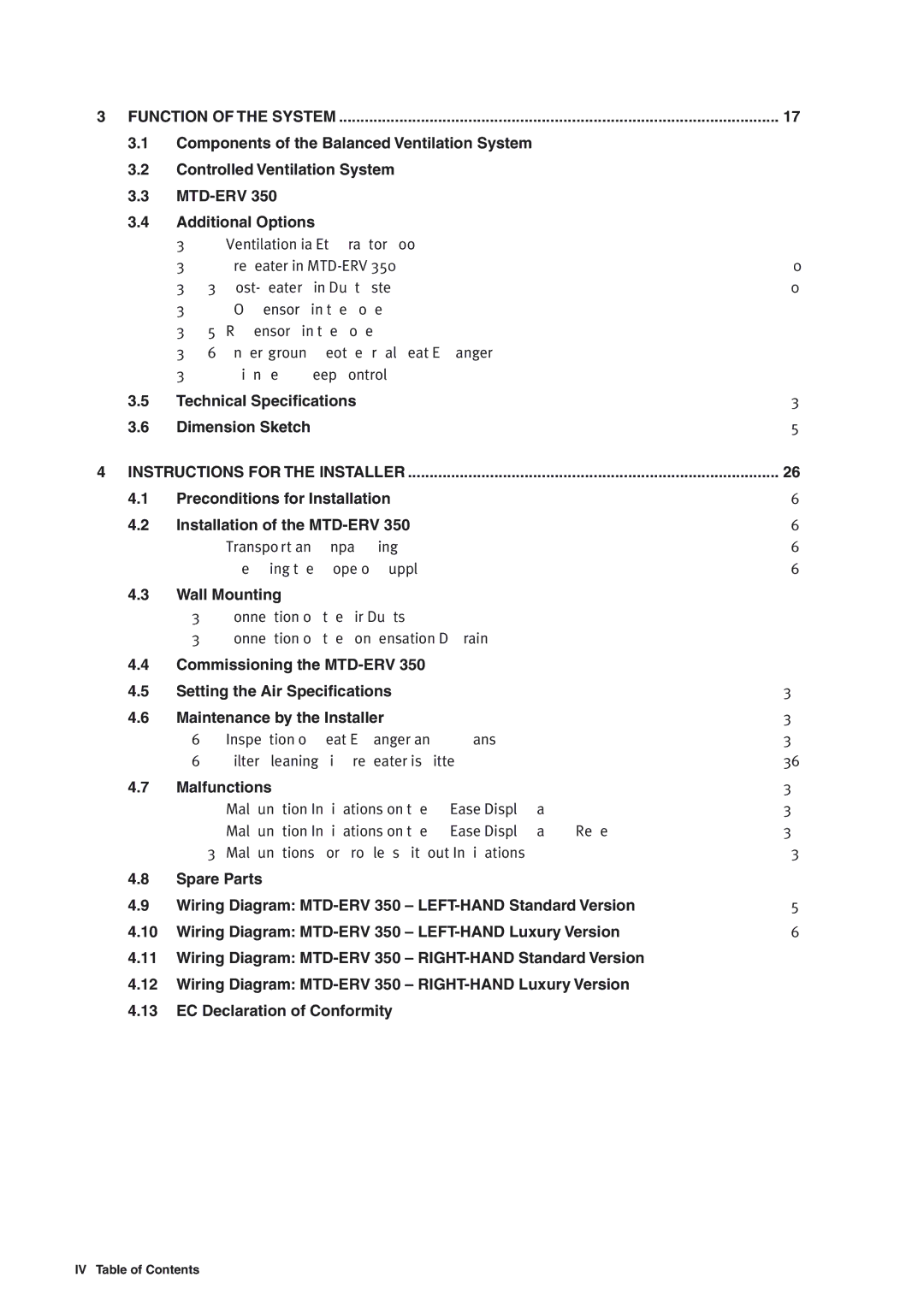
ERV 350, ERV 365 specifications
The MTD ERV 365 and ERV 350 are advanced energy recovery ventilation (ERV) systems designed to enhance indoor air quality and energy efficiency in residential and commercial buildings. These units utilize cutting-edge technologies to transfer heat and moisture between incoming and outgoing air streams, optimizing the temperature and humidity levels of the conditioned air.One of the main features of the MTD ERV 365 is its high energy recovery efficiency. Equipped with a specially designed heat exchanger, this ERV can reclaim a significant portion of the energy from the exhaust air, reducing the heating and cooling load on HVAC systems. This results in lower energy bills and decreased environmental impact. The ERV 350 offers similar benefits but is tailored for slightly smaller spaces, making it suitable for various residential applications.
Both models are constructed with durability in mind, featuring robust housing and weather-resistant materials that ensure long-lasting performance. The MTD ERV series is designed to withstand varying environmental conditions, ensuring reliable operation in challenging climates. Additionally, noise-reduction technology minimizes operational sounds, promoting a peaceful indoor environment.
User-friendly controls are another highlight of the MTD ERV systems. They come equipped with intuitive interfaces, allowing users to easily adjust settings, monitor performance, and receive maintenance notifications. Advanced sensors provide real-time data on indoor air quality parameters, ensuring optimal operation based on the specific needs of the environment.
Installation and maintenance are made straightforward with these ERV units. They feature a compact design that facilitates integration into existing HVAC systems or new constructions. Filters are easily accessible for routine cleaning or replacement, maintaining peak performance over time.
Furthermore, both the MTD ERV 365 and ERV 350 are designed with sustainability in mind. Using materials that are recyclable and energy-efficient components contributes to a reduced carbon footprint. These ERV systems also comply with various building codes and standards, ensuring they meet industry requirements for safety and efficiency.
In summary, the MTD ERV 365 and ERV 350 are sophisticated energy recovery ventilation solutions that combine advanced technologies and user-friendly features. With high energy recovery efficiency, durable construction, and easy integration, they stand out as models for improving indoor air quality and energy efficiency in a variety of settings.
