RouteFinder
Cabling your RouteFinder
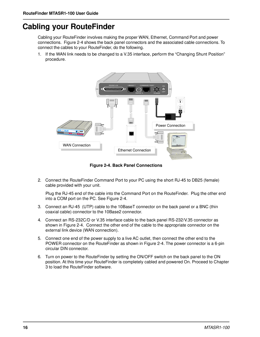
Cabling your RouteFinder involves making the proper WAN, Ethernet, Command Port and power connections. Figure
1.If the WAN link needs to be changed to a V.35 interface, perform the “Changing Shunt Position” procedure.
RS232/V.35 | 10BASE T | COMMAND PORT | ON |
OFF
10BASE 2 |
| POWER | ||
|
|
|
|
|
|
|
|
|
|
|
|
|
|
|
Power Connection
WAN Connection
Ethernet Connection
Figure 2-4. Back Panel Connections
2.Connect the RouteFinder Command Port to your PC using the short
Plug the
3.Connect an
4.Connect an
5.Connect one end of the power supply to a live AC outlet, then connect the other end to the POWER connector on the RouteFinder as shown in Figure
6.Turn on power to the RouteFinder by setting the ON/OFF switch on the back panel to the ON position. At this time your RouteFinder is completely cabled and powered On. Proceed to Chapter 3 to load the RouteFinder software.
16 |
|