Chapter 1 - Introduction and Description
Back Panel
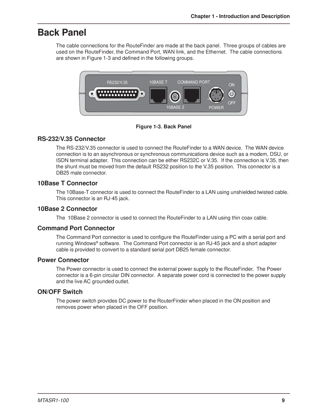
The cable connections for the RouteFinder are made at the back panel. Three groups of cables are used on the RouteFinder, the Command Port, WAN link, and the Ethernet. The cable connections are shown in Figure
RS232/V.35 | 10BASE T | COMMAND PORT | ON | |
|
|
|
| |
| 10BASE 2 | POWER | OFF | |
|
| |||
Figure 1-3. Back Panel
RS-232/V.35 Connector
The
10Base T Connector
The
10Base 2 Connector
The 10Base 2 connector is used to connect the RouteFinder to a LAN using thin coax cable.
Command Port Connector
The Command Port connector is used to configure the RouteFinder using a PC with a serial port and running Windows® software. The Command Port connector is an
Power Connector
The Power connector is used to connect the external power supply to the RouteFinder. The Power connector is a
ON/OFF Switch
The power switch provides DC power to the RouterFinder when placed in the ON position and removes power when placed in the OFF position.
9 |
