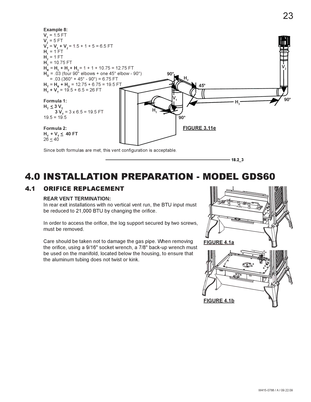
Example 8: |
|
| ||||
V1 | = 1.5 FT |
|
| |||
V2 | = 5 FT |
|
| |||
V | T | = V | 1 | + V = 1.5 + 1 + 5 = 6.5 FT |
| |
|
| 2 |
|
| ||
H1 | = 1 FT |
|
| |||
H2 | = 1 FT |
|
| |||
H3 | = 10.75 FT |
| ||||
HR | = H1 | + H2 | + H3 = 1 + 1 + 10.75 = 12.75 FT | 90° | ||
HO | = .03 (four 90° elbows + one 45° elbow - 90°) | |||||
|
| = .03 (360° + 45° - 90°) = 6.75 FT | H2 | |||
HT | = HR | + HO | = 12.75 + 6.75 = 19.5 FT | 45° | ||
HT | + VT | = 19.5 + 6.5 = 26 FT |
| |||
Formula 1: |
| V1 | ||||
|
| |||||
H |
| < 3 V |
|
| ||
| T | 3 VTT = 3 x 6.5 = 19.5 FT | H1 | |||
19.5 = 19.5 |
| 90° | ||||
Formula 2: | FIGURE 3.11e |
HT + VT < 40 FT |
|
26 < 40 |
|
Since both formulas are met, this vent configuration is acceptable.
23
V2 |
H3![]() 90°
90°
18.2_3
4.0 INSTALLATION PREPARATION - MODEL GDS60
4.1 ORIFICE REPLACEMENT
REAR VENT TERMINATION:
In rear exit installations with no vertical vent run, the BTU input must be reduced to 21,000 BTU by changing the orifice.
In order to access the orifice, the log support secured by two screws, must be removed.
Care should be taken not to damage the gas pipe. When removing | FIGURE 4.1a |
the orifice, using a 9/16" socket wrench, a 7/8" |
|
be used on the manifold, located below the housing, to ensure that |
|
the aluminum tubing does not twist or kink. |
|
