Installing the EtherSpeedII Switch Modules
If an EtherSpeedII
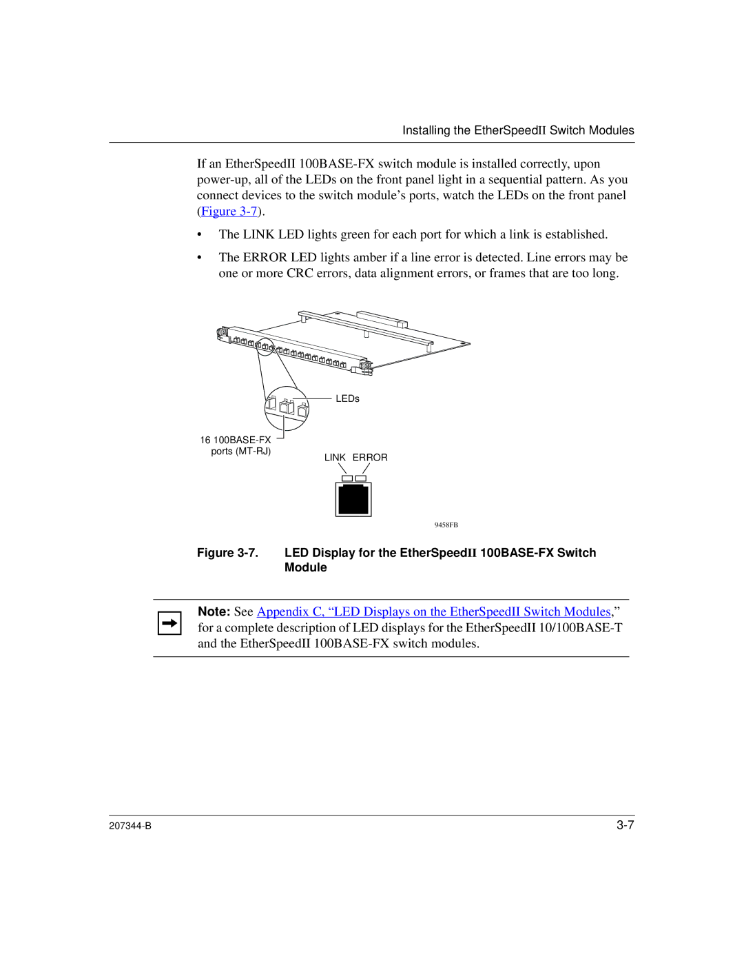
•The LINK LED lights green for each port for which a link is established.
•The ERROR LED lights amber if a line error is detected. Line errors may be one or more CRC errors, data alignment errors, or frames that are too long.
16
LEDs
LINK ERROR
9458FB
Figure 3-7. LED Display for the EtherSpeedII 100BASE-FX Switch Module
Note: See Appendix C, “LED Displays on the EtherSpeedII Switch Modules,” for a complete description of LED displays for the EtherSpeedII
|