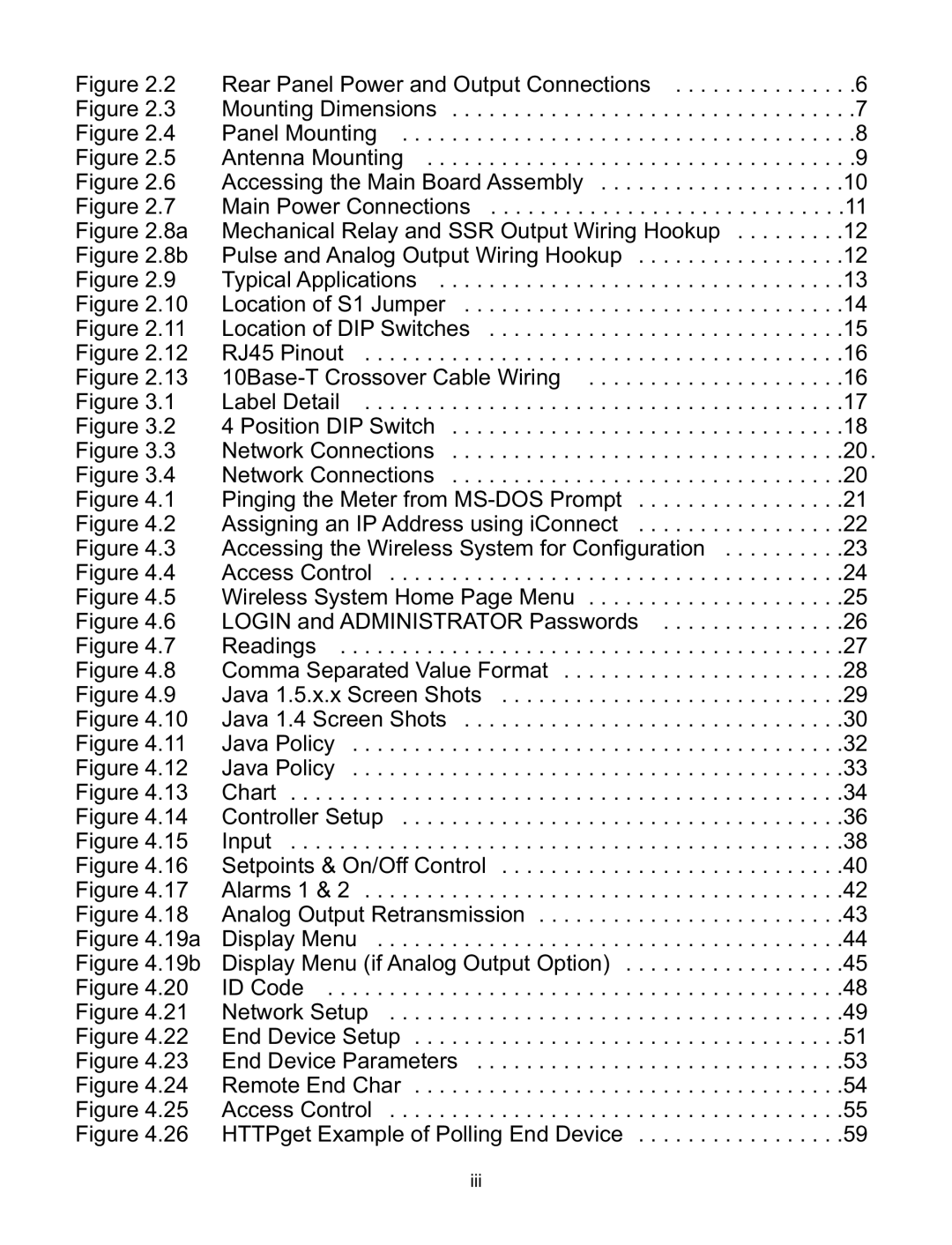
Figure 2.2
Figure 2.3
Figure 2.4
Figure 2.5
Figure 2.6
Figure 2.7
Figure 2.8a
Figure 2.8b
Figure 2.9
Figure 2.10
Figure 2.11
Figure 2.12
Figure 2.13
Figure 3.1
Figure 3.2
Figure 3.3
Figure 3.4
Figure 4.1
Figure 4.2
Figure 4.3
Figure 4.4
Figure 4.5
Figure 4.6
Figure 4.7
Figure 4.8
Figure 4.9
Figure 4.10
Figure 4.11
Figure 4.12
Figure 4.13
Figure 4.14
Figure 4.15
Figure 4.16
Figure 4.17
Figure 4.18
Figure 4.19a
Figure 4.19b
Figure 4.20
Figure 4.21
Figure 4.22
Figure 4.23
Figure 4.24
Figure 4.25
Figure 4.26
Rear Panel Power and Output Connections | . .6 |
Mounting Dimensions | . .7 |
Panel Mounting | . .8 |
Antenna Mounting | . .9 |
Accessing the Main Board Assembly | .10 |
Main Power Connections | .11 |
Mechanical Relay and SSR Output Wiring Hookup | .12 |
Pulse and Analog Output Wiring Hookup | .12 |
Typical Applications | .13 |
Location of S1 Jumper | .14 |
Location of DIP Switches | .15 |
RJ45 Pinout | .16 |
| .16 |
Label Detail | .17 |
4 Position DIP Switch | .18 |
Network Connections | .20. |
Network Connections | .20 |
Pinging the Meter from | .21 |
Assigning an IP Address using iConnect | .22 |
Accessing the Wireless System for Configuration | .23 |
Access Control | .24 |
Wireless System Home Page Menu | .25 |
LOGIN and ADMINISTRATOR Passwords | .26 |
Readings | .27 |
Comma Separated Value Format | .28 |
Java 1.5.x.x Screen Shots | .29 |
Java 1.4 Screen Shots | .30 |
Java Policy | .32 |
Java Policy | .33 |
Chart | .34 |
Controller Setup | .36 |
Input | .38 |
Setpoints & On/Off Control | .40 |
Alarms 1 & 2 | .42 |
Analog Output Retransmission | .43 |
Display Menu | .44 |
Display Menu (if Analog Output Option) | .45 |
ID Code | .48 |
Network Setup | .49 |
End Device Setup | .51 |
End Device Parameters | .53 |
Remote End Char | .54 |
Access Control | .55 |
HTTPget Example of Polling End Device | .59 |
iii
