DV-CP802
Contents
Avis
Important Safety Instructions
For models having a power cord with a polarized plug
Precautions
Sur les modèles dont la fiche est polarisée
Precautions
DV-CP802 Features
Supplied Accessories
Introduction
Introduction Disc Notes
Introduction
Disc Content Organization
MP3 & Jpeg Compatibility
Handling Discs
Terminology
Storing Discs
Copyright
Compressed digital video format used for VCDs
Jpeg Joint Photographic Experts Group
MPEG2 Moving Picture Experts Group
Vlsc Vector Linear Shaping Circuitry
Front Panel
Getting to Know the DV-CP802
Getting to Know the DV-CP802 Display
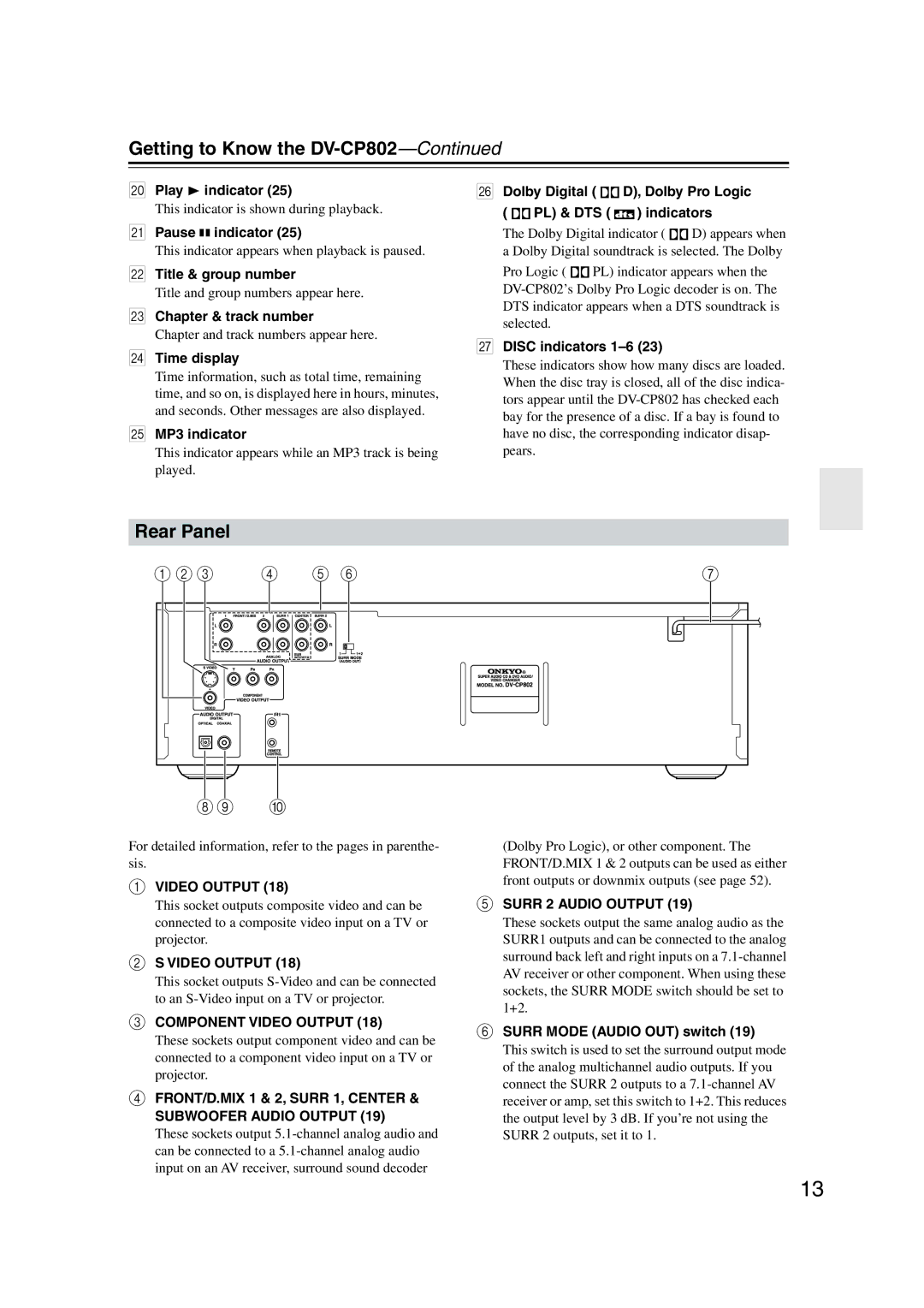
Rear Panel
Getting to Know the DV-CP802
Remote Controller
Audio button
Setup button
Angle button
Fast Forward button
Installing the Remote’s Batteries
Before Using the DV-CP802
Using the Remote Controller
Open the battery compartment, as shown
AV Cables & Connectors
Connecting the DV-CP802
Before Making Any Connections
Optical Digital Output
Video cable * supplied
Connecting the DV-CP802 Connecting Your TV or Projector
Analog Audio Connection
Connecting the DV-CP802 Connecting an AV Receiver
Dolby Digital, DTS, DVD-Audio & Sacd
Connecting Components with
Connecting the DV-CP802 Connecting a Stereo Amp
Analog Connection
Digital Connection
First Time Setup
Turning On the DV-CP802 & First Time Setup
Connect the power cord to a suit- able wall outlet
Turning On the DV-CP802
Use the Left and Right
Turning On the DV-CP802 & First Time Setup
Basic Playback
When you’ve finished, press the OPEN/CLOSE button again
Loading Discs
Press the OPEN/CLOSE button
Selecting Discs
Basic Playback
Loading Discs During Playback
Use the Disc Select 1-6 but- tons to select loaded discs
Pause To pause playback, press Pause button
Starting, Pausing & Stopping Playback
Stop
Button
Load and select a DVD-Video, DVD-Audio, or VCD disc
Navigating Disc Menus
See pages 23
Use the number buttons to spec- ify a chapter or title
Selecting Titles & Chapters by Number
For example, to enter 2, press the 2 button
Load and select a DVD-Video disc
Use the Up and Down / buttons
Using the Disc Navigator
To select tracks in the open folder
TOP Menu button
Press the Stop button to stop Playback
Memory Playback in the Disc Navigator
With the Disc Navigator open, press the Memory button
Playlist appears in place of the file Memory information
Use the number buttons to enter a track number
Selecting Tracks by Number
Load and select a DVD-Audio, SACD, VCD, CD, or MP3 disc
During playback, press the Search button
Basic Playback Fast Forward & Reverse
Slow-motion Playback
Adjusting the Display Brightness
Load and select a Jpeg CD
Using Jpeg CDs
You can use the following func- tions during the slideshow
To stop the slideshow, press the Stop or Menu button
Using Chain Mode
Time Search
Advanced Playback
Repeat Playback
Press the Search button twice
Press the Play button to start
Advanced Playback
Advanced Playback Random Playback
To cancel random playback, use
Select a disc
Random button to select Off
Press the Memory button
Memory Playback
Press the Enter button
Repeat steps 2 and 3 to add more items to the list
Deleting Items from the Memory List
Inserting New Items into the Memory List
Changing Items in the Memory List
Selecting Camera Angles
Selecting Languages & Audio Formats
Using Progressive Scanning
Selecting Subtitles
Press the Progressive but Ton
Displaying Information
Using Last Memory
1st press
Normal
2nd press
3rd press
1st press2
VCD & CD
3rd press2
Press the DV-CP802’s Video Circuit OFF button
Advanced Playback Turning Off the Video Circuits
To turn the video circuitry back on, press the button again
Configuring the DV-CP802
Menu Setting Description Picture
Audio
Language
Setup
Menu Setting Description
Configuring the DV-CP802
Operation
Picture Menu
Using the Onscreen Setup Menus
TV Shape
Interlaced Setting
Audio Menu
Progressive Setting
Digital Out/Digital1 optical output
Linear PCM Out
Digital Out/Digital2 coaxial output
Analog Audio Out
Setting the Speaker Settings
Setting the Speaker Distances
AV Synchronization
Setting Levels With the Test Tone
Selecting the AV Synchronization
CD Audio Setup
Sacd Audio Setup
Dynamic Range Control Dolby Digital Only
On-Screen Language
Configuring the DV-CP802 Language Menu
Disc Menu Language
Audio Language
Operation Menu
Configuring the DV-CP802 Display Menu
Auto power off
Priority Contents
Title/Group Stop
Language Code List
Configuring the DV-CP802 Initial Setup Menu
Selecting Other Languages
Language Code
Symptom Possible cause Remedy
Troubleshooting
Restoring the Default Settings
Troubleshooting
Abnormal Behavior
Specifications
Specifications and features subject to change without notice
Page
3 4 3 7 1
Page
Page
Page

 D), Dolby Pro Logic
 PL) & DTS (
  ) indicators