Connections
S Video input |
|
Video input |
|
Analog audio | L (white) |
input |
|
| R (red) |
6. VCR (VIDEO 1)
| R (red) |
Analog audio |
|
output | L (white) |
Video output |
|
S Video output |
|
DIGITAL |
| PR | AUDIO | VIDEO | S VIDEO | COMPONENT |
OUTPUT |
| RENNA | VIDEO | |||
|
|
|
| |||
OPT | FRONT |
|
|
| MONITOR | OUTPUT |
1 |
|
|
|
| OUT | Y |
|
|
| R | L |
|
|
| SUB |
|
|
|
|
|
2 |
|
| AM | OUT | ZONE 2 | PB |
COAX | SURR |
|
|
|
|
|
1 |
|
|
| IN | DVD | PR |
| SURR |
|
|
|
|
|
| BACK/ |
|
|
|
| INPUT 1 |
| ZONE 2 |
|
|
|
| |
2 |
| FM | OUT |
| Y | |
|
|
| ||||
|
| 75 |
| |||
|
|
|
|
|
| |
|
|
|
|
| VIDEO 1 |
|
3 | FRONT |
|
| IN |
| PB |
| O |
|
| |||
|
|
|
|
|
| |
OPT | SUB | L |
|
|
|
|
|
|
|
|
| ||
1 |
|
| PH | OUT |
| PR |
| SURR |
|
|
| VIDEO 2 | INPUT 2 |
|
|
|
|
| ||
2 |
|
| CD | IN |
| Y |
| SURR |
| OUT |
|
|
|
| BACK |
|
|
|
| |
|
|
|
|
|
| |
3 |
|
|
| IN | VIDEO 3 | PB |
RTAPE
4 |
|
|
| IN |
| VIDEO 4 | PR |
| GND | L | IN | L |
|
|
|
DIGITAL |
| R | VIDEO | S VIDEO |
| ||
| O |
| AUDIO |
| |||
INPUT |
|
|
|
|
|
|
|
7.Settop box, video camera (VIDEO 3)
R (red) |
|
| Analog audio |
L (white) | output |
Video output
S Video output
Digital audio output (optical)
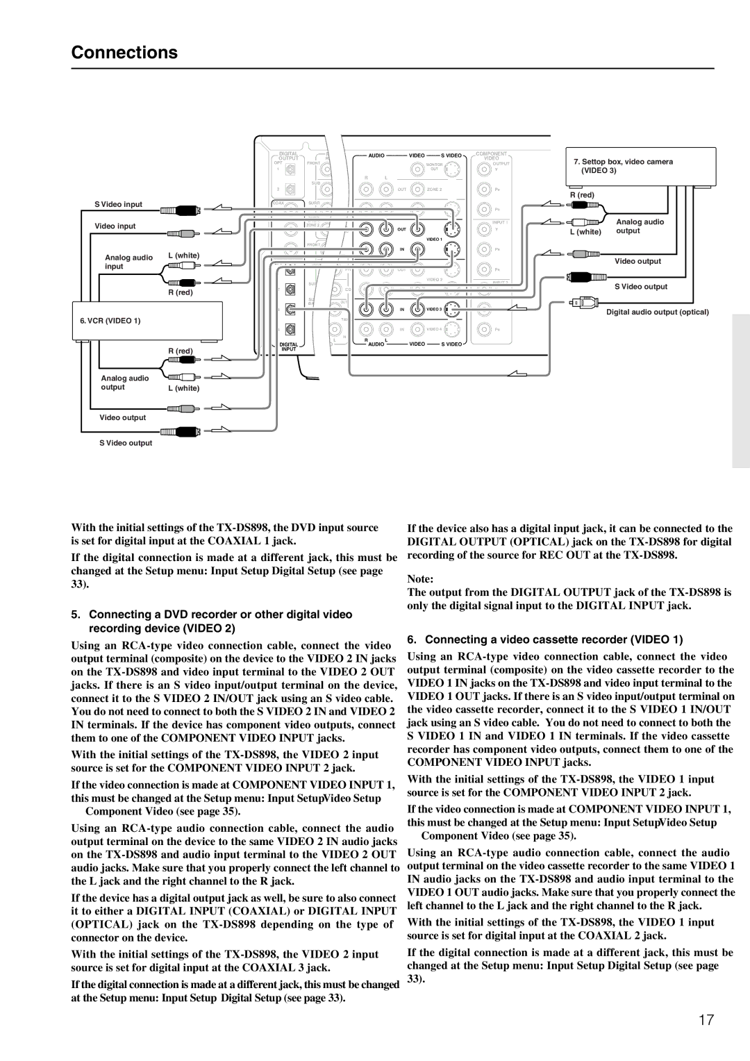
With the initial settings of the
If the digital connection is made at a different jack, this must be changed at the Setup menu: Input Setup → Digital Setup (see page 33).
5.Connecting a DVD recorder or other digital video recording device (VIDEO 2)
Using an
With the initial settings of the
If the video connection is made at COMPONENT VIDEO INPUT 1, this must be changed at the Setup menu: Input Setup → Video Setup
→Component Video (see page 35).
Using an
If the device has a digital output jack as well, be sure to also connect it to either a DIGITAL INPUT (COAXIAL) or DIGITAL INPUT (OPTICAL) jack on the
With the initial settings of the
If the digital connection is made at a different jack, this must be changed at the Setup menu: Input Setup → Digital Setup (see page 33).
If the device also has a digital input jack, it can be connected to the DIGITAL OUTPUT (OPTICAL) jack on the
Note:
The output from the DIGITAL OUTPUT jack of the
6. Connecting a video cassette recorder (VIDEO 1)
Using an
With the initial settings of the
If the video connection is made at COMPONENT VIDEO INPUT 1, this must be changed at the Setup menu: Input Setup → Video Setup
→Component Video (see page 35).
Using an
With the initial settings of the
If the digital connection is made at a different jack, this must be changed at the Setup menu: Input Setup → Digital Setup (see page 33).
17