Connections
9. TV monitor or projector | Y | |
(MONITOR OUT) | ||
| ||
Component video input | PB | |
| PR |
Video input |
S Video input |
DIGITAL |
| PR | AUDIO | VIDEO | S VIDEO | COMPONENT |
OUTPUT |
| RENNA | VIDEO | |||
|
|
|
| |||
OPT | FRONT |
|
|
| MONITOR | OUTPUT |
1 |
|
|
|
| OUT | Y |
|
|
| R | L |
|
|
| SUB |
|
|
|
|
|
2 |
|
| AM | OUT | ZONE 2 | PB |
|
|
| ||||
COAX | SURR |
|
|
|
|
|
1 |
|
|
| IN | DVD | PR |
| SURR |
|
|
|
|
|
| BACK/ |
|
|
|
| INPUT 1 |
| ZONE 2 |
|
|
|
| |
2 |
| FM | OUT |
| Y | |
|
| 75 |
| |||
|
|
|
|
|
|
8.Satellite tuner or television (VIDEO 4)
Digital audio output (optical)
|
|
| VIDEO 1 | |
3 | FRONT | IN | PB | |
IO | ||||
|
|
| ||
OPT | L |
|
| |
SUB |
|
| ||
1 | PH | OUT | PR | |
|
|
| VIDEO 2 | |
| SURR |
| INPUT 2 | |
2 | CD | IN | Y |
R (red)
L (white)
Analog audio output
| SURR | OUT |
|
|
| BACK |
|
| |
|
|
|
| |
3 |
| IN | VIDEO 3 | PB |
RTAPE
4 |
|
|
| IN |
| VIDEO 4 | PR |
| GND | L | IN | L |
|
|
|
DIGITAL |
| R | VIDEO | S VIDEO |
| ||
| IO |
| AUDIO |
| |||
INPUT |
|
|
|
|
|
|
|
Video output
S Video output
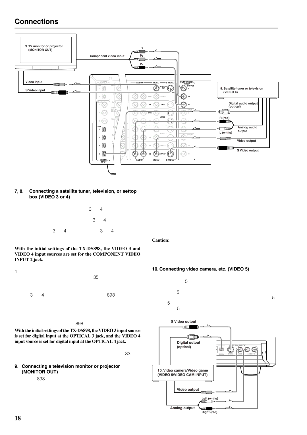
7, 8. Connecting a satellite tuner, television, or settop box (VIDEO 3 or 4)
If the satellite tuner or television is equipped with an S video output terminal, connect it to the S VIDEO 3 (or 4) IN terminal with an S video cable. If it does not have an S video output terminal, connect its video output terminal to the VIDEO 3 (or 4) IN terminal using an
With the initial settings of the
If the video connection is made at COMPONENT VIDEO INPUT 1, this must be changed at the Setup menu: Input Setup → Video Setup → Component Video (see page 35).
Using an
If the device has a digital output jack as well, be sure to also connect it to either a DIGITAL INPUT (COAXIAL) or DIGITAL INPUT (OPTICAL) jack on the
If the monitor or projector is equipped with an S video output terminal, connect it to the MONITOR OUT S VIDEO terminal with an S video cable. If it does not have an S video output terminal, connect its video output terminal to the MONITOR OUT VIDEO terminal using an
Caution:
Note that the Setup menu will only be displayed on the monitor connected to MONITOR OUT and not those connected to the COMPONENT VIDEO OUTPUT jacks.
10. Connecting video camera, etc. (VIDEO 5)
If the device is equipped with an S video output terminal, connect it to the S VIDEO 5 IN terminal with an S video cable. If it does not have an S video output terminal, connect its video output terminal to the VIDEO 5 IN terminal using an
The VIDEO 5 digital input is fixed to the OPTICAL input on the front panel.
S Video output
With the initial settings of the |
|
|
|
|
|
is set for digital input at the OPTICAL 3 jack, and the VIDEO 4 |
|
|
|
|
|
input source is set for digital input at the OPTICAL 4 jack. | Digital output |
| VIDEO 5/VIDEO CAM INPUT |
| |
If the digital connection is made at a different jack, this must be changed | (optical) | N |
| ||
|
|
| |||
at the Setup menu: Input Setup → Digital Setup (see page 33). |
| DIGITAL | S VIDEO | VIDEO | L AUDIO R |
9. Connecting a television monitor or projector | 10. Video camera/Video game |
|
|
|
|
(MONITOR OUT) |
|
|
|
| |
| (VIDEO 5/VIDEO CAM INPUT) |
|
|
|
|
The
Video output ![]()
Left (white)
Analog output
Right (red)
18