Operating components not reached by the remote controller signals (IR IN/OUT)
The following equipment (sold separately) is essential for operation:
•Onkyo’s
•Multiroom A/V distribution and control systems from Niles® and Xantech® to name a few
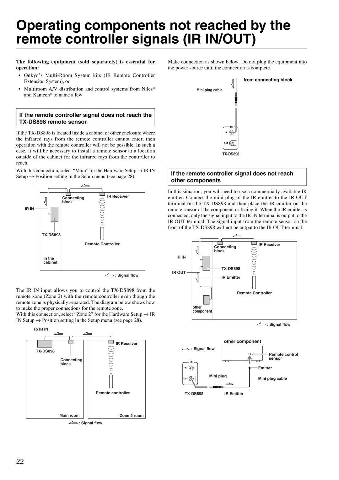
Make connection as shown below. Do not plug the equipment into the power source until the connection is complete.
from connecting block
Mini plug cable ![]()
If the remote controller signal does not reach the
If the
With this connection, select “Main” for the Hardware Setup → IR IN Setup → Position setting in the Setup menu (see page 28).
I R
IN
OUT
If the remote controller signal does not reach other components
IR IN
Connecting | IR Receiver |
block |
|
In this situation, you will need to use a commercially available IR emitter. Connect the mini plug of the IR emitter to the IR OUT terminal on the
In the cabinet
Remote Controller
Connecting block
IR IN
IR Receiver
![]()
![]() : Signal flow
: Signal flow
The IR IN input allows you to control the
With this connection, select “Zone 2” for the Hardware Setup → IR IN Setup → Position setting in the Setup menu (see page 28).
To IR IN
IR Receiver
Connecting block
Remote controller
Main room | Zone 2 room |
![]() : Signal flow
: Signal flow
IR OUT
IR Emitter
Remote Controller
other component
![]() : Signal flow
: Signal flow
other component
![]() : Signal flow
: Signal flow
|
| Remote control |
|
| sensor |
I R |
|
|
IN |
| Emitter |
OUT | Mini plug | Mini plug cable |
| ||
IR Emitter |
|
22