Parts and their functions (continued)
Display panel
1 |
|
|
|
| 2 |
|
|
|
| 3 |
|
| 4 |
|
|
| 6 | 8 7 | 9 |
|
|
| ||||||||||||||||||||||||||||||
|
|
|
|
|
|
|
|
|
|
|
|
|
|
|
|
|
|
|
|
|
|
|
|
|
|
|
|
|
|
|
| 5 |
|
|
|
|
|
|
|
|
|
|
|
|
|
|
| |||||
|
|
|
|
|
|
|
|
|
|
|
|
|
|
|
|
|
|
|
|
|
|
|
|
|
|
|
|
|
|
|
|
|
|
|
|
|
|
|
|
|
|
|
|
|
|
|
|
|
|
|
|
|
|
|
|
|
|
|
|
|
|
|
|
|
|
|
|
|
|
|
|
|
|
|
|
|
|
|
|
|
|
|
|
| SCH | SERVO |
|
|
|
|
|
|
|
| |||||||||||
525 |
|
| 625 |
| WIDE |
|
|
|
| REMOTE |
| VIDEO |
|
| AUDIO |
|
|
|
|
|
|
|
|
| ||||||||||||||||||||||||||||
|
|
|
|
|
|
|
|
|
|
|
|
|
| |||||||||||||||||||||||||||||||||||||||
dB | dB |
|
| dB | dB |
|
|
|
|
|
|
|
|
| Y PB PR |
| ANALOG |
|
|
|
|
|
|
|
|
|
|
|
|
|
|
|
|
| ||||||||||||||||||
0 |
|
|
| 0 |
| 0 |
|
|
|
| 0 |
|
|
| CUE |
|
| CMPST |
| AES/EBU |
| U |
| = |
| EDIT REC | INH | |||||||||||||||||||||||||
|
|
|
|
|
|
|
|
|
| |||||||||||||||||||||||||||||||||||||||||||
|
|
|
|
|
|
|
|
|
| dB |
|
|
|
|
| USER SET | DVCPRO |
|
|
|
|
|
|
| ||||||||||||||||||||||||||||
|
|
|
|
|
|
|
|
|
|
|
|
| SDI |
| SDI |
|
|
|
|
|
|
| ||||||||||||||||||||||||||||||
|
|
|
|
|
|
|
|
|
|
|
|
|
|
|
|
| 50 |
|
|
|
|
|
|
|
|
|
|
|
| |||||||||||||||||||||||
|
|
|
|
|
|
|
|
|
|
|
| SDTI/1394 | SDTI/1394 |
|
|
|
|
|
|
|
|
|
|
|
|
| ||||||||||||||||||||||||||
|
|
|
|
|
|
|
|
|
|
|
|
| DVCAM |
|
|
|
|
|
|
| ||||||||||||||||||||||||||||||||
|
|
|
|
|
|
|
|
|
|
|
|
|
|
|
|
|
|
|
|
|
|
|
|
|
|
|
|
| SG 1 2 |
| SG |
|
|
|
|
|
|
|
| |||||||||||||
|
|
|
|
|
|
|
|
|
|
|
|
|
|
|
|
|
|
|
|
|
| |||||||||||||||||||||||||||||||
|
|
|
|
|
|
|
|
|
|
|
|
|
|
|
|
|
|
|
|
|
|
|
|
|
|
|
|
|
|
| ||||||||||||||||||||||
|
|
|
|
|
|
|
|
|
|
|
|
|
|
|
|
|
|
|
|
|
|
|
|
|
|
|
|
|
|
|
|
|
|
|
|
| ||||||||||||||||
|
|
|
|
|
|
|
|
|
|
| CTL |
|
|
|
|
|
|
|
|
|
|
|
|
|
|
|
|
|
|
|
|
| ||||||||||||||||||||
|
|
|
|
|
|
|
|
|
|
|
|
|
|
|
|
|
|
|
|
|
|
|
|
|
|
|
|
|
|
|
| |||||||||||||||||||||
|
|
|
|
|
|
|
|
|
|
|
| TC |
|
|
|
|
|
|
|
|
|
|
|
|
|
|
|
|
|
|
|
|
| |||||||||||||||||||
- |
|
|
|
| - |
|
| - |
|
|
|
| - |
| - |
|
|
|
|
|
|
|
|
|
|
|
|
|
|
|
|
|
|
|
|
|
|
|
|
| ||||||||||||
|
|
|
|
|
|
|
|
|
|
|
|
|
| UB |
|
|
|
|
|
|
|
|
|
|
|
|
|
|
|
|
|
|
|
|
| |||||||||||||||||
| L |
| R |
| L |
| R |
| L |
| R |
| L |
| R |
| L |
| R |
|
|
|
|
|
|
|
|
|
|
|
|
|
|
|
|
|
|
|
|
| ||||||||||||
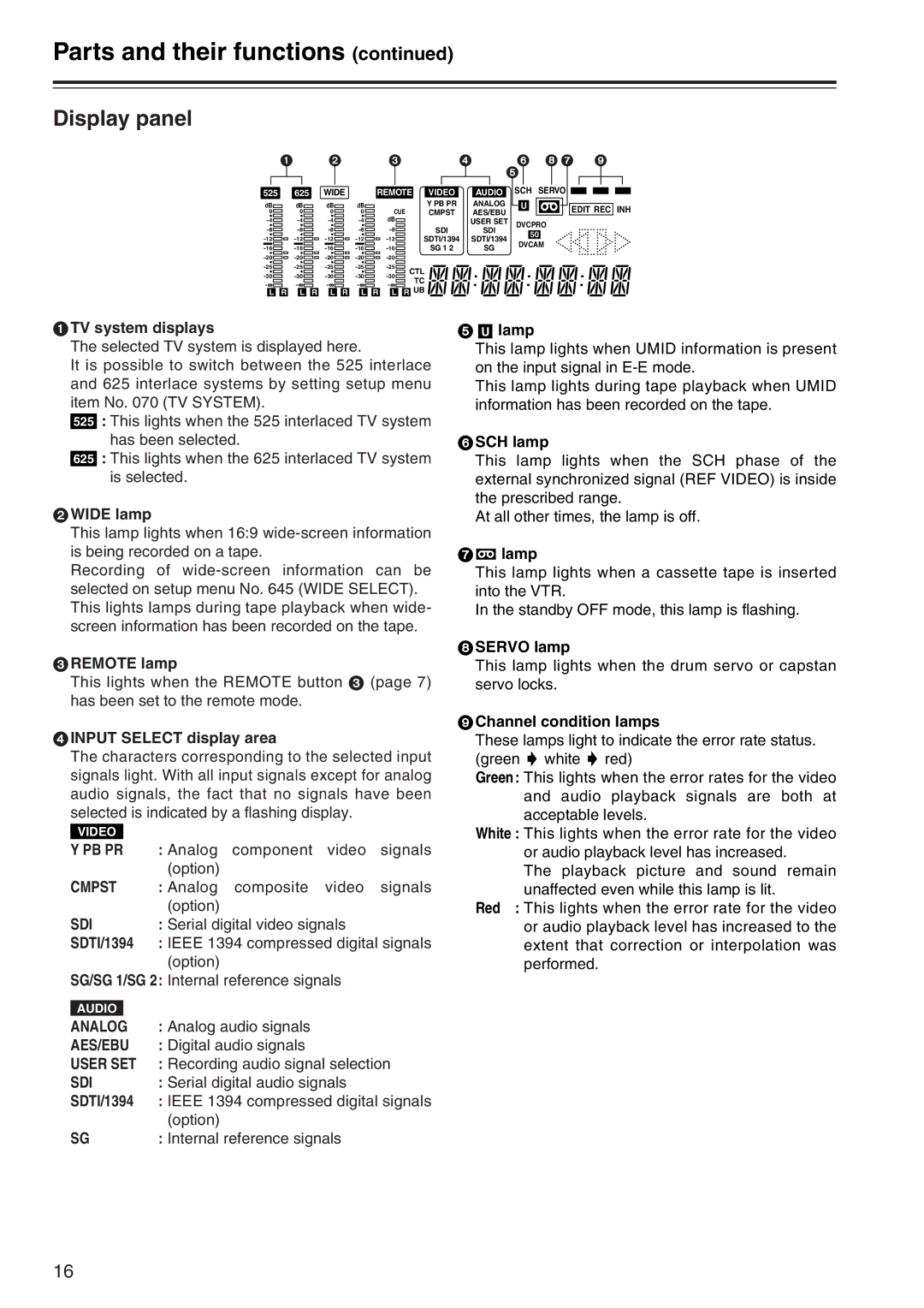
1TV system displays
The selected TV system is displayed here.
It is possible to switch between the 525 interlace and 625 interlace systems by setting setup menu item No. 070 (TV SYSTEM).
525 : This lights when the 525 interlaced TV system has been selected.
625 : This lights when the 625 interlaced TV system is selected.
2WIDE lamp
This lamp lights when 16:9
Recording of
3REMOTE lamp
This lights when the REMOTE button 3 (page 7) has been set to the remote mode.
4INPUT SELECT display area
The characters corresponding to the selected input signals light. With all input signals except for analog audio signals, the fact that no signals have been
selected is indicated by a flashing display.
VIDEO |
|
|
Y PB PR | : Analog component video signals | |
|
| (option) |
CMPST | : Analog composite video signals | |
|
| (option) |
SDI | : Serial digital video signals | |
SDTI/1394 | : IEEE 1394 compressed digital signals | |
|
| (option) |
SG/SG 1/SG 2: Internal reference signals
5U lamp
This lamp lights when UMID information is present on the input signal in
This lamp lights during tape playback when UMID information has been recorded on the tape.
6SCH lamp
This lamp lights when the SCH phase of the external synchronized signal (REF VIDEO) is inside the prescribed range.
At all other times, the lamp is off.
7= lamp
This lamp lights when a cassette tape is inserted into the VTR.
In the standby OFF mode, this lamp is flashing.
8SERVO lamp
This lamp lights when the drum servo or capstan servo locks.
9Channel condition lamps
These lamps light to indicate the error rate status. (green 5 white 5 red)
Green: This lights when the error rates for the video and audio playback signals are both at acceptable levels.
White : This lights when the error rate for the video
or audio playback level has increased.
The playback picture and sound remain unaffected even while this lamp is lit.
Red : This lights when the error rate for the video or audio playback level has increased to the extent that correction or interpolation was performed.
AUDIO |
|
|
ANALOG | : Analog audio signals | |
AES/EBU | : Digital audio signals | |
USER SET | : Recording audio signal selection | |
SDI | : Serial digital audio signals | |
SDTI/1394 | : IEEE 1394 compressed digital signals | |
|
| (option) |
SG | : Internal reference signals | |
16