Parts and their functions
Front panel
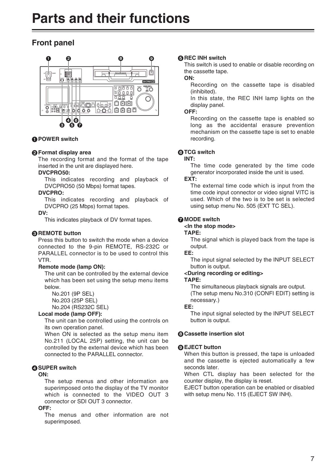
1 | 2 | 8 | 9 |
5REC INH switch |
This switch is used to enable or disable recording on |
ONPOWER
OFF
HEADPHONES | AUDIO MIX | |
1&2 |
| 3&4 |
CH1/3 | CH2/4 | REC CH1/3 |
PULL | CH2/4 | REC CH2/4 |
CH1/3 | ||
|
|
|
|
|
|
|
|
|
|
|
|
|
|
|
| EJECT |
|
| DVCPRO 50 |
|
|
|
|
|
|
|
|
|
|
| |||
2X |
| DVCPRO |
|
|
|
|
|
|
|
|
|
|
|
|
| |
|
| DV |
|
|
|
|
|
|
|
|
|
|
|
|
|
|
REMOTE |
| SUPER | REC INH | TCG | MODE |
|
|
|
|
|
|
|
|
|
|
|
|
| ON | ON | INT | TAPE |
|
|
|
|
|
|
|
|
|
|
|
|
| OFF | OFF | EXT | EE |
|
|
|
|
|
|
|
|
|
|
|
|
|
|
|
|
|
|
|
|
| COUNTER | ASSEM | VIDEO | CUE | TC | SEARCH | SHTL SLOW |
|
|
|
|
|
|
|
|
|
|
|
|
|
|
|
| PUSH |
|
|
|
|
|
|
|
|
|
|
| INSERT |
|
|
|
| JOG |
|
|
|
|
|
|
|
|
|
| RESET | CH 1 | CH 2 | CH 3 | CH 4 |
| |
|
|
|
|
|
|
|
|
|
|
| PF 1 | PF 2 | PF 3 | PF 4 |
|
|
|
|
|
|
|
|
|
|
|
| STAND BY | PLAYER | RECORDER |
| SET |
|
|
|
|
|
|
|
|
|
|
|
|
| TC PRESET | MENU |
| PF |
|
|
|
|
|
|
|
|
|
|
|
| EDIT |
| PLAY | REC |
|
|
|
|
|
| METER | INPUT SELECT | PREVIEW/ | AUTO EDIT PREROLL |
|
|
|
|
|
|
|
|
| |
|
|
| REVIEW | A IN |
| A OUT |
|
|
|
|
|
| ||||
AUDIO MON SEL | FULL/FINE VIDEO | AUDIO |
|
|
|
|
|
|
|
|
|
|
| |||
|
|
|
|
|
|
|
|
|
|
|
|
|
| |||
MIX | L | R | CH 1 | CH 2 | CH 3 | CH 4 | IN | SET | REW |
| STOP | FF |
| SHIFT |
| |
OUT |
|
|
|
|
| |||||||||||
REC |
| UNITY |
|
|
|
|
|
|
|
|
|
|
|
|
| PULL |
PB VAR
AUDIO VOL SEL
46
3 5 7
the cassette tape. |
ON: |
Recording on the cassette tape is disabled |
(inhibited). |
In this state, the REC INH lamp lights on the |
display panel. |
OFF: |
Recording on the cassette tape is enabled so |
long as the accidental erasure prevention |
mechanism on the cassette tape is set to enable |
1POWER switch
2Format display area
The recording format and the format of the tape inserted in the unit are displayed here.
DVCPRO50:
This indicates recording and playback of DVCPRO50 (50 Mbps) format tapes.
DVCPRO:
This indicates recording and playback of DVCPRO (25 Mbps) format tapes.
DV:
This indicates playback of DV format tapes.
3REMOTE button
Press this button to switch the mode when a device connected to the
Remote mode (lamp ON):
The unit can be controlled by the external device which has been set using the setup menu items below.
No.201 (9P SEL) No.203 (25P SEL) No.204 (RS232C SEL)
Local mode (lamp OFF):
The unit can be controlled using the controls on its own operation panel.
When ON is selected as the setup menu item No.211 (LOCAL 25P) setting, the unit can be controlled by the external device which has been connected to the PARALLEL connector.
4SUPER switch ON:
The setup menus and other information are superimposed onto the display of the TV monitor which is connected to the VIDEO OUT 3 connector or SDI OUT 3 connector.
OFF:
The menus and other information are not superimposed.
recording. |
6TCG switch INT:
The time code generated by the time code generator incorporated inside the unit is used.
EXT:
The external time code which is input from the time code input connector or video signal VITC is used. Which of the two is to be set is selected using setup menu No. 505 (EXT TC SEL).
7MODE switch
<In the stop mode> TAPE:
The signal which is played back from the tape is output.
EE:
The input signal selected by the INPUT SELECT button is output.
<During recording or editing> TAPE:
The simultaneous playback signals are output. (The setup menu No.310 (CONFI EDIT) setting is necessary.)
EE:
The input signal selected by the INPUT SELECT button is output.
8Cassette insertion slot
9EJECT button
When this button is pressed, the tape is unloaded and the cassette is ejected automatically a few seconds later.
When CTL display has been selected for the counter display, the display is reset.
EJECT button operation can be enabled or disabled with setup menu No. 115 (EJECT SW INH).
7