Parts and their functions (continued)
Rear panel
12 3 45 6 7 8 9: ;
AES/EBU |
| ANALOG | REMOTE |
| ANALOG |
|
|
|
| |||
CH1/2 |
|
| VIDEO |
|
|
|
|
|
|
|
| SDI |
IN |
|
| IN |
|
|
|
|
|
|
|
| |
AC IN |
|
| REMOTE IN/OUT | CH1 PUSH AUDIO PUSH CH2 | PUSH | TC | IN | OUT | ||||
|
|
| ON | |||||||||
|
|
|
|
|
|
| IN |
|
| IN |
|
|
CH3/4 | Y |
| 75Ω |
|
|
|
|
|
|
|
|
|
|
|
|
|
|
|
|
|
|
|
| 1 | |
IN |
|
| OFF |
|
|
|
|
|
|
|
| |
|
|
|
| REMOTE | OUT |
|
|
|
|
|
|
|
| PB |
|
|
|
| CH3 PUSH |
| PUSH CH4 |
| TC |
| ACTIVE |
|
|
|
|
|
|
|
| THROUGH | ||||
CH1/2 |
|
| REF VIDEO |
|
|
|
|
|
| OUT |
| 2 |
OUT |
|
| IN |
|
|
|
|
|
|
|
| |
|
|
| ON | ENCODER REMOTE |
|
|
|
|
|
|
| |
|
|
|
|
|
|
|
|
|
|
|
| |
CH3/4 | PR |
| 75Ω |
|
|
|
|
|
|
|
| 3 |
OPTION |
|
|
|
|
|
|
|
|
|
| ||
OUT |
| OFF |
|
| CH1 | AUDIO | CH2 |
| MON |
| (SUPER) | |
|
|
|
|
|
| OUT |
|
| L |
|
| |
|
|
|
|
|
|
|
|
|
|
|
| OPTION |
Y |
| 1 | VIDEO |
|
|
|
|
|
|
|
|
|
|
|
| OUT |
|
|
|
|
|
|
|
|
|
|
|
|
| PARALLEL |
|
|
|
|
| MON |
|
|
|
|
|
|
|
| CH3 |
| CH4 |
|
|
| |
PB |
| 2 |
|
|
|
|
|
|
| R |
|
|
| (WFM) |
|
|
|
|
|
|
|
|
|
| |
PR |
| 3 |
|
|
|
|
|
|
|
|
|
|
(SUPER) |
|
|
|
|
|
|
|
|
|
| ||
SIGNAL |
|
|
|
|
|
|
|
|
|
|
|
|
GND |
|
|
|
|
|
|
|
|
|
|
|
|
SERVICE ONLY |
|
|
|
|
|
|
|
|
|
| ||
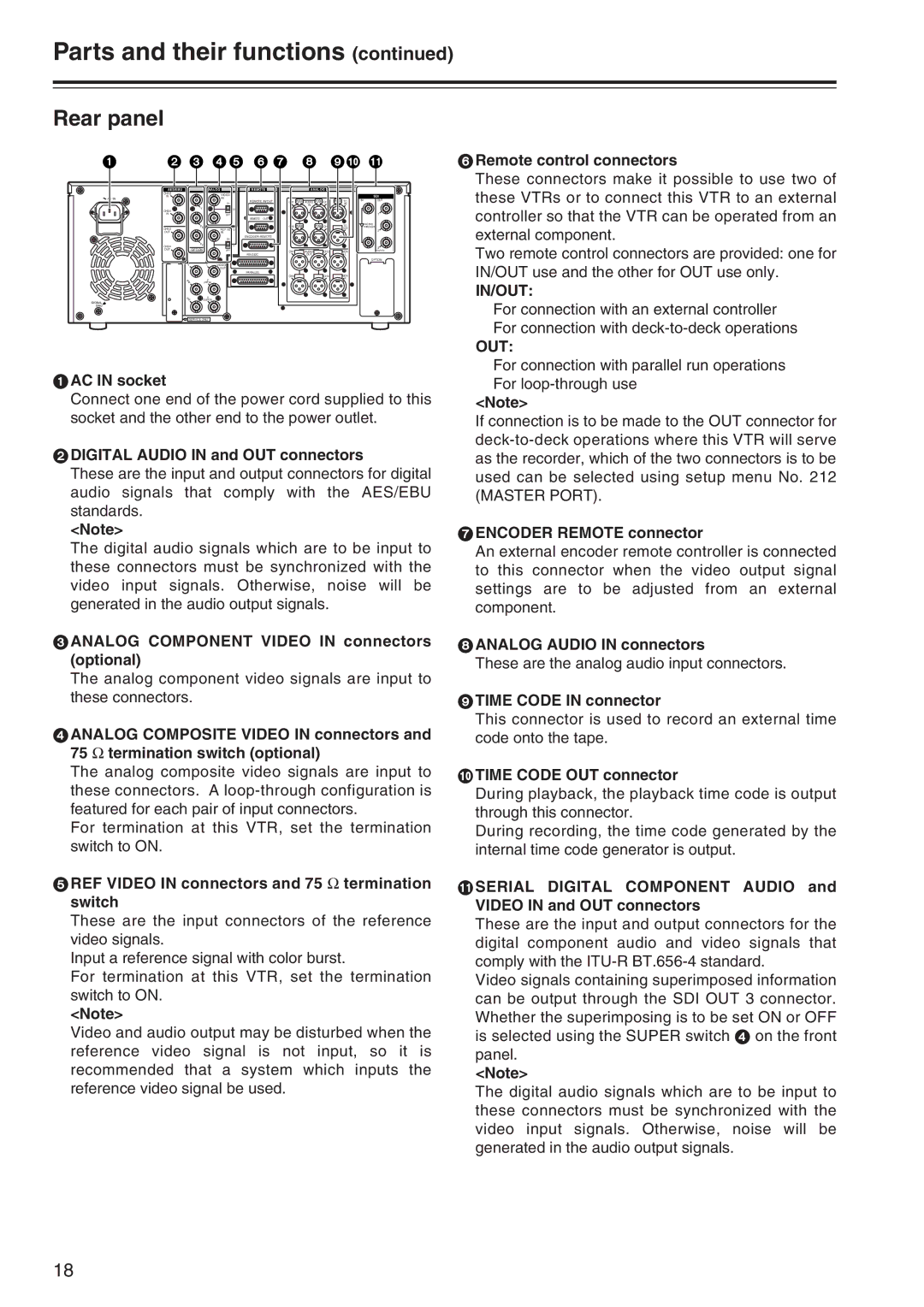
1AC IN socket
Connect one end of the power cord supplied to this socket and the other end to the power outlet.
2DIGITAL AUDIO IN and OUT connectors
These are the input and output connectors for digital audio signals that comply with the AES/EBU standards.
<Note>
The digital audio signals which are to be input to these connectors must be synchronized with the video input signals. Otherwise, noise will be generated in the audio output signals.
3ANALOG COMPONENT VIDEO IN connectors (optional)
The analog component video signals are input to these connectors.
4ANALOG COMPOSITE VIDEO IN connectors and 75 Ω termination switch (optional)
The analog composite video signals are input to these connectors. A
For termination at this VTR, set the termination switch to ON.
5REF VIDEO IN connectors and 75 Ω termination switch
These are the input connectors of the reference video signals.
Input a reference signal with color burst.
For termination at this VTR, set the termination switch to ON.
<Note>
Video and audio output may be disturbed when the reference video signal is not input, so it is recommended that a system which inputs the reference video signal be used.
6Remote control connectors
These connectors make it possible to use two of these VTRs or to connect this VTR to an external controller so that the VTR can be operated from an external component.
Two remote control connectors are provided: one for IN/OUT use and the other for OUT use only.
IN/OUT:
For connection with an external controller For connection with
OUT:
For connection with parallel run operations For
<Note>
If connection is to be made to the OUT connector for
7ENCODER REMOTE connector
An external encoder remote controller is connected to this connector when the video output signal settings are to be adjusted from an external component.
8ANALOG AUDIO IN connectors
These are the analog audio input connectors.
9TIME CODE IN connector
This connector is used to record an external time code onto the tape.
:TIME CODE OUT connector
During playback, the playback time code is output through this connector.
During recording, the time code generated by the internal time code generator is output.
;SERIAL DIGITAL COMPONENT AUDIO and VIDEO IN and OUT connectors
These are the input and output connectors for the digital component audio and video signals that comply with the
Video signals containing superimposed information can be output through the SDI OUT 3 connector. Whether the superimposing is to be set ON or OFF is selected using the SUPER switch 4 on the front panel.
<Note>
The digital audio signals which are to be input to these connectors must be synchronized with the video input signals. Otherwise, noise will be generated in the audio output signals.
18