Parts and their functions (continued)
Front panel
Q P |
|
|
| R |
|
|
|
|
|
|
|
|
|
|
|
| |||||
|
|
|
|
|
|
|
|
|
|
|
|
|
|
|
|
|
|
|
|
| EJECT |
ON | POWER |
|
|
| DVCPRO 50 |
|
|
|
|
|
|
|
|
|
|
|
| ||||
| 2X |
| DVCPRO |
|
|
|
|
|
|
|
|
|
|
| |||||||
|
|
|
|
|
|
|
|
|
|
|
|
|
|
|
|
|
|
| |||
|
|
|
|
|
| DV |
|
|
|
|
|
|
|
|
|
|
|
|
|
|
|
OFF |
|
|
| REMOTE |
| SUPER | REC INH | TCG | MODE |
|
|
|
|
|
|
|
|
|
|
|
|
|
|
|
|
| ON | ON | INT | TAPE |
|
|
|
|
|
|
|
|
|
|
|
| |
|
|
|
|
|
| OFF | OFF | EXT | EE |
|
|
|
|
|
|
|
|
|
|
|
|
|
|
|
|
|
|
|
|
|
|
|
|
|
|
| COUNTER | ASSEM | VIDEO | CUE | TC | SEARCH | SHTL SLOW |
|
|
|
|
|
|
|
|
|
|
|
|
|
|
|
|
|
|
|
|
| PUSH |
|
|
|
|
|
|
|
|
|
|
|
|
|
|
|
| INSERT |
|
|
|
| JOG |
|
|
|
|
|
|
|
|
|
|
|
|
|
|
| RESET | CH 1 | CH 2 | CH 3 | CH 4 |
| |
|
|
|
|
|
|
|
|
|
|
|
|
|
|
|
| PF 1 | PF 2 | PF 3 | PF 4 |
|
|
|
|
|
|
|
|
|
|
|
|
|
|
|
|
| STAND BY | PLAYER | RECORDER |
| SET |
|
|
|
|
|
|
|
|
|
|
|
|
|
|
|
|
|
| TC PRESET | MENU |
| PF |
|
|
|
|
|
|
|
|
|
|
|
|
|
|
|
|
| EDIT |
| PLAY | REC |
|
|
|
|
|
|
|
|
|
| METER | INPUT SELECT | PREVIEW/ | AUTO EDIT PREROLL |
|
|
|
|
|
|
|
|
|
| |
|
|
|
|
|
|
| REVIEW | A IN |
| A OUT |
|
|
|
|
|
|
| ||||
HEADPHONES |
| AUDIO MIX | AUDIO MON SEL | FULL/FINE VIDEO | AUDIO |
|
|
|
|
|
|
|
|
|
|
|
| ||||
|
|
|
|
|
|
|
|
|
|
|
|
|
|
|
| ||||||
| 1&2 |
| 3&4 |
|
|
|
|
|
|
|
|
|
|
| REW |
| STOP | FF |
|
|
|
| CH1/3 | CH2/4 | REC CH1/3 | MIX | L | R | CH 1 | CH 2 | CH 3 | CH 4 | IN | SET | OUT |
|
| SHIFT |
| ||||
PULL | CH1/3 | CH2/4 | REC CH2/4 | REC |
| UNITY |
|
|
|
|
|
|
|
|
|
|
|
|
|
| PULL |
|
|
|
| PB |
| VAR |
|
|
|
|
|
|
|
|
|
|
|
|
|
|
|
AUDIO VOL SEL
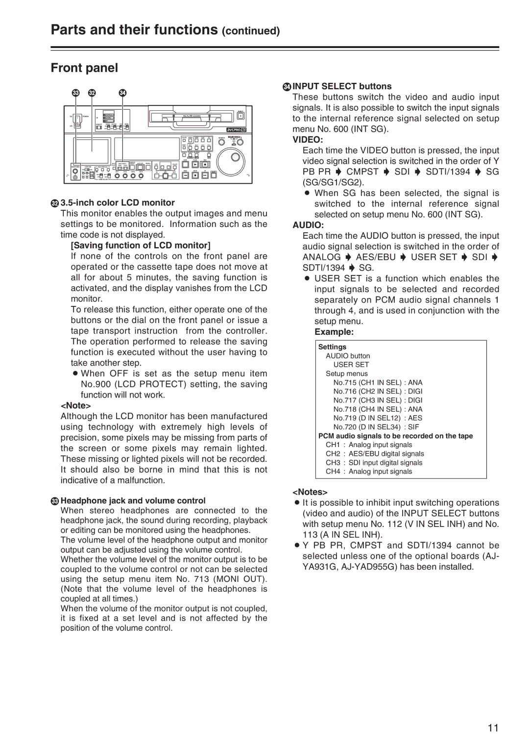
P3.5-inch color LCD monitor
This monitor enables the output images and menu settings to be monitored. Information such as the time code is not displayed.
[Saving function of LCD monitor]
If none of the controls on the front panel are operated or the cassette tape does not move at all for about 5 minutes, the saving function is activated, and the display vanishes from the LCD monitor.
To release this function, either operate one of the buttons or the dial on the front panel or issue a tape transport instruction from the controller. The operation performed to release the saving function is executed without the user having to take another step.
O When OFF is set as the setup menu item No.900 (LCD PROTECT) setting, the saving function will not work.
<Note>
Although the LCD monitor has been manufactured using technology with extremely high levels of precision, some pixels may be missing from parts of the screen or some pixels may remain lighted. These missing or lighted pixels will not be recorded. It should also be borne in mind that this is not indicative of a malfunction.
QHeadphone jack and volume control
When stereo headphones are connected to the headphone jack, the sound during recording, playback or editing can be monitored using the headphones.
The volume level of the headphone output and monitor output can be adjusted using the volume control. Whether the volume level of the monitor output is to be coupled to the volume control or not can be selected using the setup menu item No. 713 (MONI OUT). (Note that the volume level of the headphones is coupled at all times.)
When the volume of the monitor output is not coupled, it is fixed at a set level and is not affected by the position of the volume control.
RINPUT SELECT buttons
These buttons switch the video and audio input signals. It is also possible to switch the input signals to the internal reference signal selected on setup menu No. 600 (INT SG).
VIDEO:
Each time the VIDEO button is pressed, the input video signal selection is switched in the order of Y PB PR 5 CMPST 5 SDI 5 SDTI/1394 5 SG (SG/SG1/SG2).
O When SG has been selected, the signal is switched to the internal reference signal selected on setup menu No. 600 (INT SG).
AUDIO:
Each time the AUDIO button is pressed, the input audio signal selection is switched in the order of
ANALOG 5 AES/EBU 5 USER SET 5 SDI 5 SDTI/1394 5 SG.
O USER SET is a function which enables the input signals to be selected and recorded separately on PCM audio signal channels 1 through 4, and is used in conjunction with the setup menu.
Example:
Settings
AUDIO button
USER SET
Setup menus
No.715 (CH1 IN SEL) : ANA
No.716 (CH2 IN SEL) : DIGI
No.717 (CH3 IN SEL) : DIGI
No.718 (CH4 IN SEL) : ANA
No.719 (D IN SEL12) : AES
No.720 (D IN SEL34) : SIF
PCM audio signals to be recorded on the tape
CH1 : Analog input signals
CH2 : AES/EBU digital signals
CH3 : SDI input digital signals
CH4 : Analog input signals
<Notes>
O It is possible to inhibit input switching operations (video and audio) of the INPUT SELECT buttons with setup menu No. 112 (V IN SEL INH) and No. 113 (A IN SEL INH).
O Y PB PR, CMPST and SDTI/1394 cannot be selected unless one of the optional boards (AJ- YA931G,
11