Connecting a television with AUDIO/VIDEO,
indicates included accessories.
indicates accessories not included.
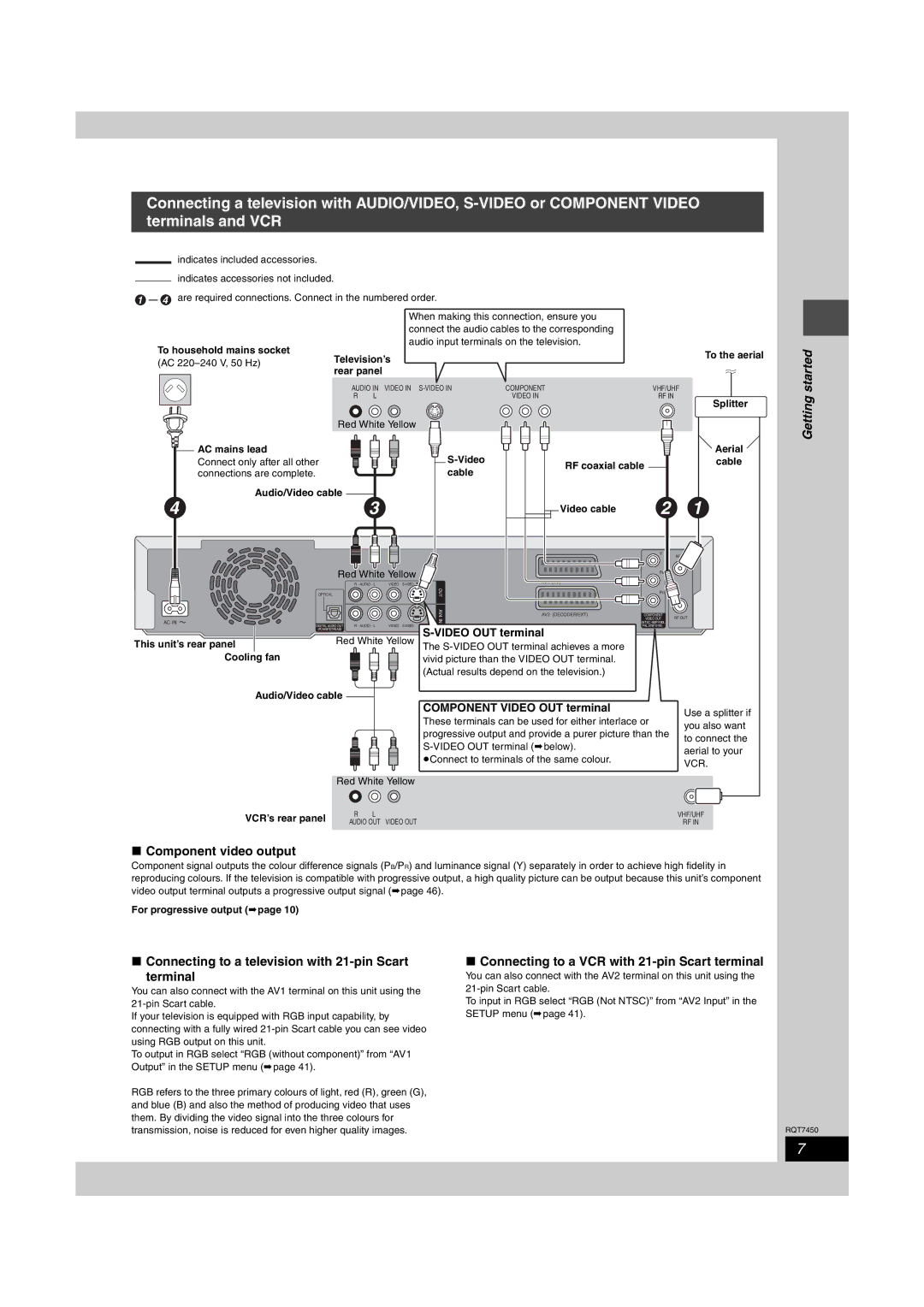
1 4 are required connections. Connect in the numbered order.
When making this connection, ensure you connect the audio cables to the corresponding audio input terminals on the television.
To household mains socket | Television’s | To the aerial | |
(AC | |||
| |||
rear panel |
| ||
|
|
started
AUDIO IN VIDEO IN
R L
COMPONENT | VHF/UHF |
VIDEO IN | RF IN |
Splitter
Getting
| Red White Yellow |
| AC mains lead |
| Connect only after all other |
| connections are complete. |
| Audio/Video cable |
4 | 3 |
| Red White Yellow |
R - AUDIO - L | VIDEO |
OPTICAL
OUT
|
| Aerial |
RF coaxial cable |
| cable |
|
| |
Video cable | 2 | 1 |
| Y | RF IN |
|
|
PB ![]()
AV1 (TV)
PR
|
|
|
| AV4 | AV2 (DECODER/EXT) | COMPONENT |
|
AC IN |
|
|
| IN |
| VIDEO OUT RF OUT | |
DIGITAL AUDIO OUT R - AUDIO - L | VIDEO |
| (NTSC:480P/480I, |
| |||
|
| PAL:576P/576I) |
| ||||
| (PCM/BITSTREAM) |
|
|
| |||
This unit’s rear panel |
| Red White Yellow |
|
| |||
| The |
|
| ||||
Cooling fan |
|
| vivid picture than the VIDEO OUT terminal. |
|
| ||
|
|
|
| (Actual results depend on the television.) |
|
| |
| Audio/Video cable |
| COMPONENT VIDEO OUT terminal |
|
| ||
|
|
|
|
| Use a splitter if | ||
|
|
|
| These terminals can be used for either interlace or | |||
|
|
|
| you also want | |||
|
|
|
| progressive output and provide a purer picture than the | |||
|
|
|
| to connect the | |||
|
|
|
|
| |||
|
|
|
|
| aerial to your | ||
|
|
|
| ≥Connect to terminals of the same colour. |
| ||
|
|
|
|
| VCR. | ||
|
|
|
|
|
|
| |
|
| Red White Yellow |
|
|
|
| |
| VCR’s rear panel | R L |
|
|
|
| VHF/UHF |
| AUDIO OUT | VIDEO OUT |
|
|
| RF IN | |
|
|
|
|
| |||
∫Component video output
Component signal outputs the colour difference signals (PB/PR) and luminance signal (Y) separately in order to achieve high fidelity in reproducing colours. If the television is compatible with progressive output, a high quality picture can be output because this unit’s component video output terminal outputs a progressive output signal (➡page 46).
For progressive output (➡page 10)
∫Connecting to a television with 21-pin Scart
terminal
You can also connect with the AV1 terminal on this unit using the
If your television is equipped with RGB input capability, by connecting with a fully wired
To output in RGB select “RGB (without component)” from “AV1 Output” in the SETUP menu (➡page 41).
RGB refers to the three primary colours of light, red (R), green (G), and blue (B) and also the method of producing video that uses them. By dividing the video signal into the three colours for transmission, noise is reduced for even higher quality images.
∫Connecting to a VCR with 21-pin Scart terminal
You can also connect with the AV2 terminal on this unit using the
To input in RGB select “RGB (Not NTSC)” from “AV2 Input” in the SETUP menu (➡page 41).
RQT7450
7