About descriptions in these operating instructions
Region number supported by this unit
Example
Digital Switchover
Easy access to various functions
≥ Connection with Hdmi terminal ≥ Deep Colour
Before use
How to replace the fuse
Table of Contents
Safety Precautions
Other Settings
Setting Menus
Advanced Editing
Reference
Remote Control Information
Remote Control Information/Unit Care
Using the remote control
Unit Care
Media Handling
Location of Parts/Controls
Remote Control
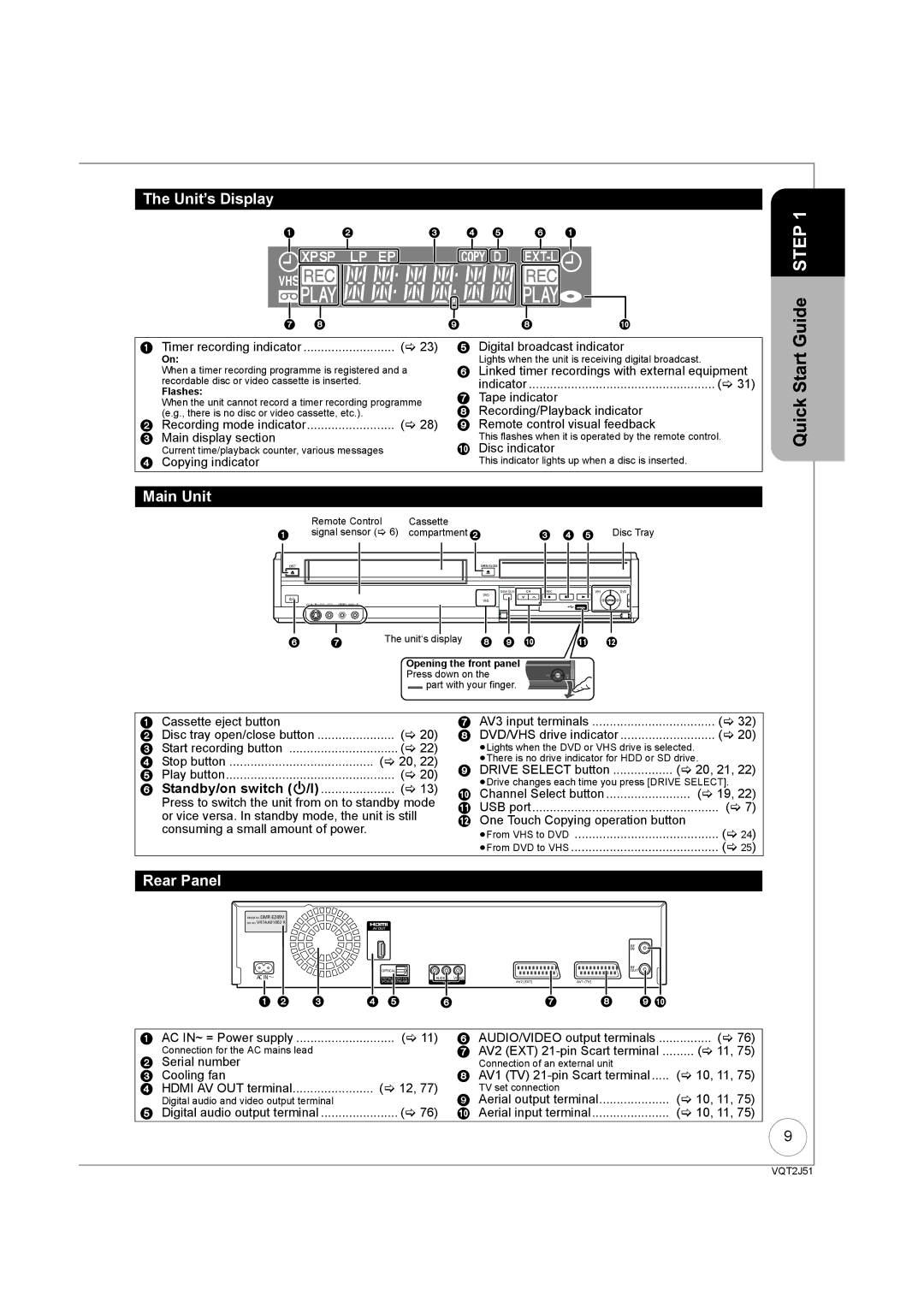
Unit’s Display
Main Unit
Rear Panel
Basic Connection
Connecting to a Television only
This unit
Pin Scart terminal
When the unit is not to be used for a long time
Connecting AC mains lead included
To view digital satellite programmes
To record digital satellite programmes
This case, make sure to switch the television input to AV
Connecting with a Panasonic TV Viera
Digital Satellite receiver
AV2 EXT AV1TV
When setup has completed, the confirmation screen appears
Setting the Channels and Clock
To cancel Auto-Setup
Preparation
Press the numbered
4 to change the setting
Buttons to enter your choice of a
Digit PIN number
Disc Handling
Usable Discs for Recording and Playback
Recording Modes and Durations
Play-only Discs
Discs that Cannot be Played
Types of disc for the type of connected TV
USB memories you can use on this unit
USB Memory Handling
MP3 File Information
Music files and Still Pictures Jpeg
Still Picture JPEG§2 Information
RDL CD
to turn the unit on TV
Watching Television
To select desired channel
To directly enter Channels
To select the DVD drive
Playback
Stopping Play
2, 1 to select an item, then OK
To select the VHS drive
Stopping Play Pausing Play
Insert a cassette
Playing a Video Cassette
Recording Television Programmes
Pausing Recording Stopping Recording
Insert a disc or video cassette
To start recording
What is FREEVIEWTM?
Timer Recording
4, 2, 1 to select the future programme, then OK
Programming
Press and hold for about 3 seconds
Copying Titles One Touch Copy
To copy without finalising
Copying Titles VHS J DVD
Copying Titles or Playlists DVD J VHS
≥When you start copying from the selected title
RAM -R -RDL -RW‹V› -RW‹VR› +R +RDL +RW VHS Preparation
To copy from a finalised disc
4 to select Delete, then OK 4 to select Video, then OK
Deleting Titles
4, 2, 1 to select the title, then Pause
To select Delete, then OK
Copy-once
Recording
Broadcast in multi-channel sound
Advanced Recording
DVD Recording Modes and Durations
VHS Recording Modes and Durations
Is reached
Repeatedly until the desired time
To select Yes, then OK
Press and hold for about 1 second
4, 2, 1 to select the title to play, then OK
4 to select Others, then OK
Flexible Recording
Playing while you are recording
Satellite receiver you have
Recording from a Digital Satellite Receiver
Connected
To select the DVD or VHS Drive
Recording from an External Device
4 to select New Timer Programme, then OK
Advanced Timer Recording
1 to move through the items To set the items
To select Stop Recording, then OK
PROG/CHECK then 3, 4 to select Programme
If the Overlapped Timer Recording screen appears
2, 1 to make changes
Then OK
Make timer programming on the TV to turn the unit off
Making timer recordings on the television
Start and end of recording is controlled by TV
Using the Guide Plus+ list
What is the Guide Plus+ system?
Guide Plus+ system
View advertisement
List of categories
Yellow to display
4 to select Free Word
Search, then OK
4, 2, 1 to select the title you want to watch, then OK
Advanced Disc Playback
4 to select the time, then OK
To fast-forward the tape. to rewind the tape
Advanced Video Cassette Playback
Twice to Jet Search forward. twice to Jet Search in reverse
More seconds
CH simultaneously
Press and hold until the picture noise disappears
Press and hold until the shaking stops
Press and hold for about 5 or More seconds
Playing Music files and Still Pictures Jpeg
2, 1 to select an album
Show Album View screen
2, 1 to select Set, then
Playing still pictures
4 to select Rotate Right or Rotate LEFT, then OK
To select Zoom in, then OK
2, 1 to select the picture
4 to select Properties, then
Function Menu Display
Convenient Functions
With the unit stopped
Change which drive is used
What is Q Link? QLink
What is Viera Link Hdavi Control? VIERALink
Press and hold ¥ Direct TV REC for 1 second
≥This unit supports Hdavi Control 5 function
Easy control only with Viera remote control
To show the screen information
Information Messages
4 to select Audio Description, then OK
4 to select Audio Description 1 to select Auto, then Return
To change the category
Entering Text
Status Several times to cycle through available displays
Entering text
Titles-Editing
Accessing the Title View
Title Operations
Refer to Title Operations right
Partial Delete
Set up Protection/Cancel Protection RAM +R +RDL +RW
Press 1 Play to start play
Press OK at the point you want to use as
Accessing the Chapter View
Chapters-Creating and Editing
Chapter Operations
Creating, Editing and Playing Playlists
Accessing the Playlist View
Creating Playlists
Editing Playlists/Chapters
Edit
Chapter View
Chapter Operations
Accessing the Album still picture/Picture View
Still Pictures-Editing
Album still picture/Picture Operations
Set up Protection/Cancel Protection
Deleting still pictures using Delete Navigator
Properties RAM -R -RDL CD USB
5a Press 3, 4, 2, 1 to select the item, then press Delete ¢
Copying Titles VHS DVD
Copying Titles or Playlists
Cancel all registered copying setting and lists
Copying Titles or Playlists DVD VHS
Register titles and playlists for copy
Copying list icons and functions
When the top menu is displayed
DVD-V VHS
Press 3, 4, 2, 1 to select the title you want to start
RAM RAM
Copying Still Pictures
Menu is automatically displayed
Register still pictures for copy
To select another folder
Press and hold Return for 3 seconds
Accessing the On-Screen Display
Setting On-Screen Display
Playback NR
Picture Menu RAM -R -RDL -RW‹V› +R +RDL +RW DVD-V -RW‹VR›
Copy NR
Sound Menu
DVD Management
Accessing the Management Menus
Create Top Menu +RW
Finalising RDL -RW‹V› +R +RDL
Setup Menu
Channel Settings
Accessing the Setup Menu
DVB Manual Tuning
DVB Auto Setup by Signal Quality DVB Auto Setup by Region
Signal Condition
Signal Strength
Playback/Recording and Picture Settings
Sound and Display Settings
Connection Settings
VHS Settings
System Settings
Software Update in Standby
System Update
Software Update Search Now
Default Settings
Other Settings
Using the Unit’s Remote Control to Operate the TV
Child Lock
Additional Connections
Using an Optical Digital Audio Cable not included
Using an Audio Cable not included
Adding an Amplifer or Receiver
Insert fully with this side up Do not bend cable sharply
Receiver
Setup
Frequently Asked Questions
Discs
Guide Plus+
Mpeg PCM
What can or cannot be done using the USB port on this unit?
On the Unit’s Display
Messages
On the TV
To Reset This Unit
Troubleshooting Guide
General Issues Displays
General Issues Power
General Issues
General Issues Operation
General Issues DVB-T
Playback Issues Picture
General Issues USB
Playback Issues Operation
Playback Issues Sound
Playback Issues VHS Picture
Playback Issues Music
Playback Issues VHS Sound
Playback Issues VHS Play
Recording Issues VHS Recording
Copying, deleting, and setting protection takes a long time
Editing Issues
Cannot format
Cannot delete chapters
DVD-R SL
Specifications
Glossary
Protection
Signal Quality
Sampling frequency
Thumbnail
This Unit is Intended for USE in Moderate Climates
For business users in the European Union
Index