Connecting the AQ-EC1 Extension Control Unit (Option)

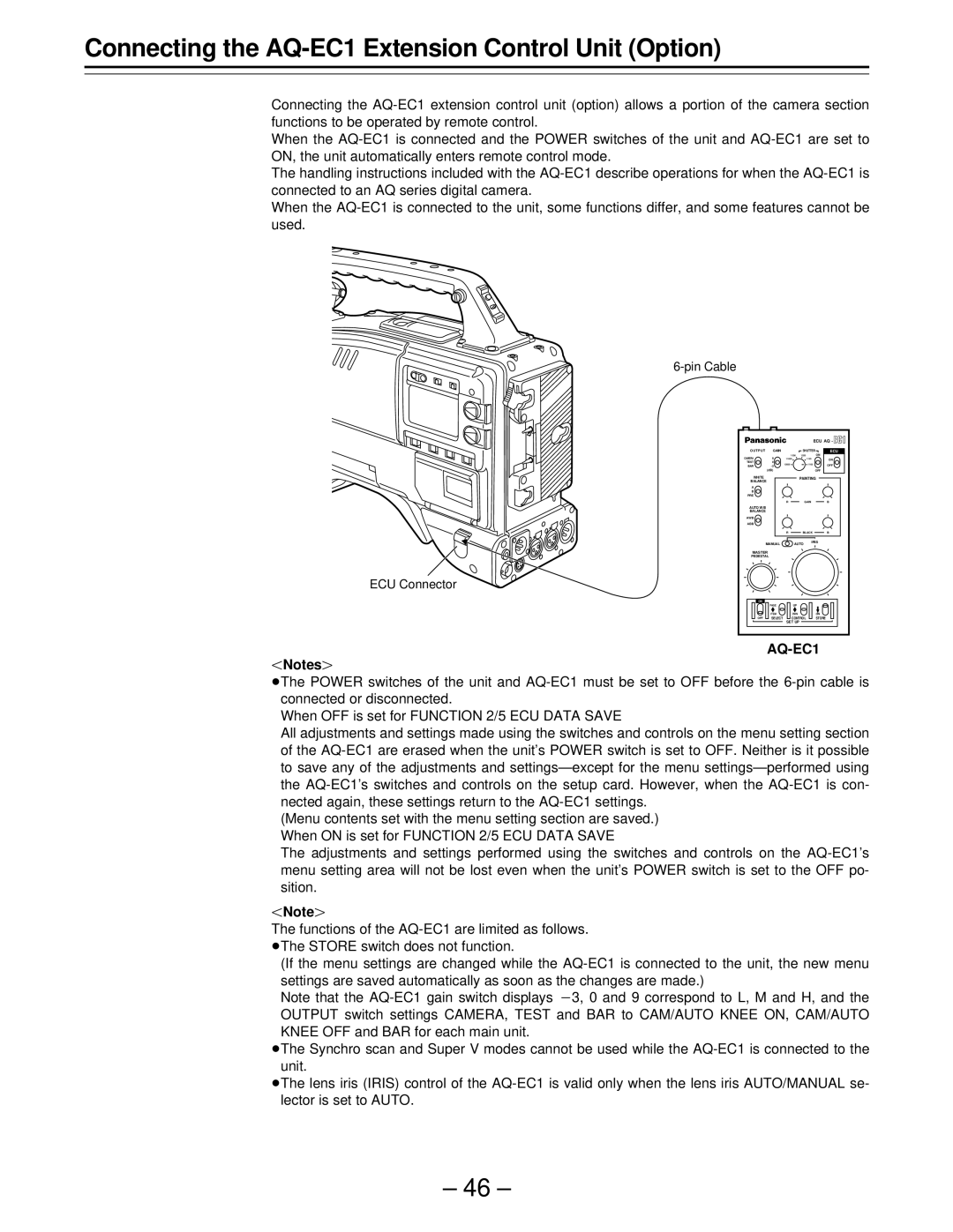
Connecting the AQ-EC1 extension control unit (option) allows a portion of the camera section functions to be operated by remote control.

When the AQ-EC1 is connected and the POWER switches of the unit and AQ-EC1 are set to ON, the unit automatically enters remote control mode.

The handling instructions included with the AQ-EC1 describe operations for when the AQ-EC1 is connected to an AQ series digital camera.

When the AQ-EC1 is connected to the unit, some functions differ, and some features cannot be used.

6-pin Cable

ECU Connector


ECU AQ -

O U T P U T

GAIN


SHUTTER

ECU

CAMERA

9


1/500

1/250


ON

1/1000


1/125

ON

TEST

0

1/2000


1/100


BAR

-3


OFF


(dB)


OFF

WHITE


PAINTING

BALANCE


A


B


PRE


R


GAIN

B

AUTO W/B


BALANCE


AWB


ABB


R


BLACK

B

MANUAL


AUTO

IRIS


MASTER


PEDESTAL


ON


PAGE


UP


ITEM


DWN


ON

OFF

SELECT


CONTROL


STORE


SET UP


AQ-EC1

Notes{

ÁThe POWER switches of the unit and AQ-EC1 must be set to OFF before the 6-pin cable is connected or disconnected.

When OFF is set for FUNCTION 2/5 ECU DATA SAVE

All adjustments and settings made using the switches and controls on the menu setting section of the AQ-EC1 are erased when the unit’s POWER switch is set to OFF. Neither is it possible to save any of the adjustments and settings—except for the menu settings—performed using the AQ-EC1’s switches and controls on the setup card. However, when the AQ-EC1 is con- nected again, these settings return to the AQ-EC1 settings.

(Menu contents set with the menu setting section are saved.) When ON is set for FUNCTION 2/5 ECU DATA SAVE

The adjustments and settings performed using the switches and controls on the AQ-EC1’s menu setting area will not be lost even when the unit’s POWER switch is set to the OFF po- sition.

Note{

The functions of the AQ-EC1 are limited as follows. ÁThe STORE switch does not function.

(If the menu settings are changed while the AQ-EC1 is connected to the unit, the new menu settings are saved automatically as soon as the changes are made.)

Note that the AQ-EC1 gain switch displays p3, 0 and 9 correspond to L, M and H, and the OUTPUT switch settings CAMERA, TEST and BAR to CAM/AUTO KNEE ON, CAM/AUTO KNEE OFF and BAR for each main unit.

ÁThe Synchro scan and Super V modes cannot be used while the AQ-EC1 is connected to the unit.

ÁThe lens iris (IRIS) control of the AQ-EC1 is valid only when the lens iris AUTO/MANUAL se- lector is set to AUTO.

– 46 –

Page 46
Image 46
Panasonic PAJ- AJ- P operating instructions Connecting the AQ-EC1 Extension Control Unit Option, Pin Cable ECU Connector