Location and function of each part (continued)
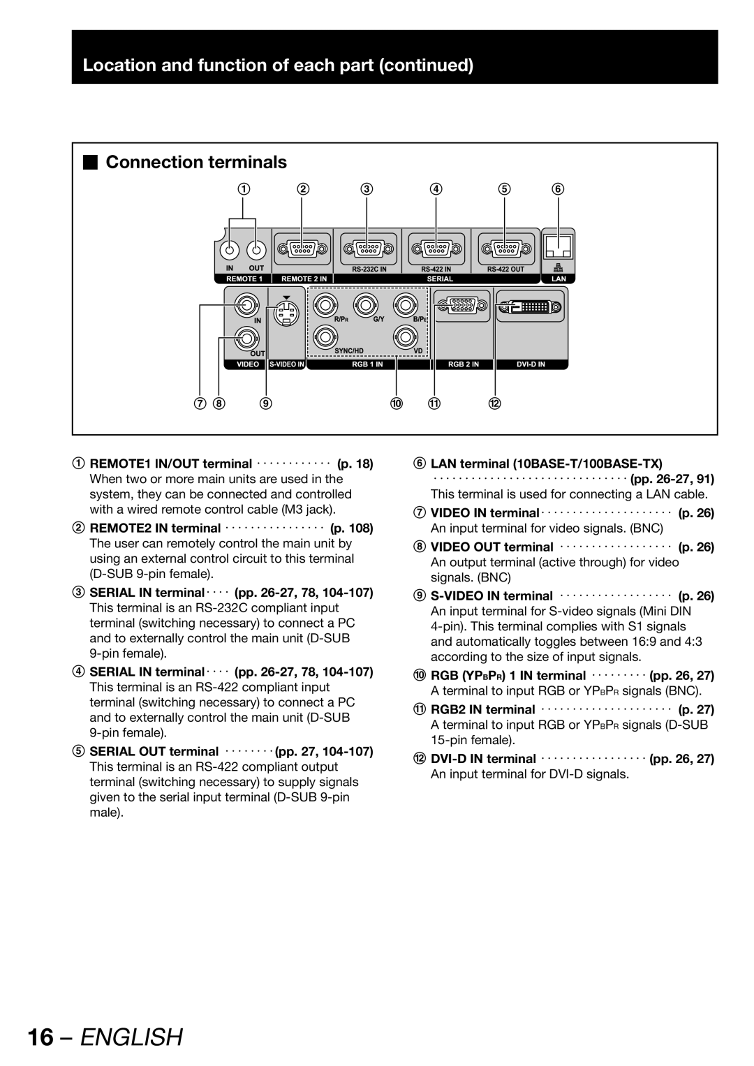
Connection terminals
|
| 1 | 2 | 3 |
|
| 4 |
|
| 5 |
| 6 |
| |||||||||||||||
|
|
|
|
|
|
|
|
|
|
|
|
|
|
|
|
|
|
|
|
|
|
|
|
|
|
|
|
|
|
|
|
|
|
|
|
|
|
|
|
|
|
|
|
|
|
|
|
|
|
|
|
|
|
|
|
|
|
|
|
|
|
|
|
|
|
|
|
|
|
|
|
|
|
|
|
|
|
|
|
|
|
|
|
|
|
|
|
|
|
|
|
|
|
|
|
|
|
|
|
|
|
|
|
|
|
|
|
|
|
|
|
|
|
|
|
|
|
|
|
|
|
|
|
|
|
|
|
|
|
|
|
|
|
|
|
|
|
|
|
|
|
|
|
|
|
|
|
|
|
|
|
|
|
|
|
|
|
|
|
|
|
|
|
|
|
|
|
|
|
|
|
|
|
|
|
|
|
|
|
|
|
|
|
|
|
|
|
|
|
|
|
|
|
|
|
|
|
|
|
|
|
|
|
|
|
|
|
|
|
|
|
|
|
|
|
|
|
|
|
|
|
|
|
|
|
|
|
|
|
|
|
|
|
|
|
|
|
|
|
|
|
|
|
|
|
|
|
|
|
|
|
|
|
|
|
|
|
|
|
|
|
|
|
|
|
|
|
|
|
|
|
|
|
|
|
|
|
|
|
|
|
|
|
|
|
|
|
|
|
|
|
|
|
|
|
|
|
|
|
|
|
|
|
|
|
|
|
|
|
|
|
|
|
|
|
|
|
|
|
|
|
|
|
|
|
|
|
|
|
|
|
|
|
|
|
|
|
|
|
|
|
|
|
|
|
|
|
|
|
|
|
|
|
|
|
|
|
|
|
|
|
|
|
|
|
|
|
|
|
|
|
|
|
|
|
|
|
|
|
|
|
|
|
|
|
|
|
|
|
|
|
|
|
|
|
|
|
|
|
|
|
|
|
|
|
|
|
|
|
|
|
|
|
|
|
|
|
|
|
|
|
|
|
|
|
|
|
|
|
|
|
|
|
|
7 8 9 | j k | l |
1REMOTE1 lN/OUT terminal ・・・・・・・・・・・・ (p. 18) When two or more main units are used in the system, they can be connected and controlled with a wired remote control cable (M3 jack).
2REMOTE2 IN terminal ・・・・・・・・・・・・・・・・ (p. 108) The user can remotely control the main unit by using an external control circuit to this terminal
3SERIAL IN terminal・・・・ (pp.
4SERIAL IN terminal・・・・ (pp.
5SERIAL OUT terminal ・・・・・・・・(pp. 27,
6LAN terminal
・・・・・・・・・・・・・・・・・・・・・・・・・・・・・・・ (pp.
7VIDEO IN terminal・・・・・・・・・・・・・・・・・・・・・ (p. 26) An input terminal for video signals. (BNC)
8VIDEO OUT terminal ・・・・・・・・・・・・・・・・・・ (p. 26) An output terminal (active through) for video signals. (BNC)
9
jRGB (YPBPR) 1 IN terminal ・・・・・・・・・ (pp. 26, 27) A terminal to input RGB or YPBPR signals (BNC).
kRGB2 IN terminal ・・・・・・・・・・・・・・・・・・・・・ (p. 27) A terminal to input RGB or YPBPR signals
l