Installation of input module (optional) (continued)
Connecting the signal to the dual link
module
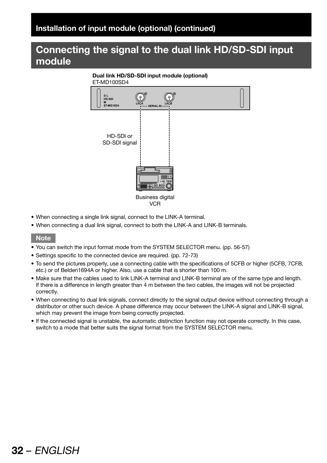
Dual link HD/SD-SDI input module (optional)
Dual Link |
|
|
|
| |
Module | ||
| SERIAL IN |
Business digital
VCR
•When connecting a single link signal, connect to the
•When connecting a dual link signal, connect to both the
Note
•You can switch the input format mode from the SYSTEM SELECTOR menu. (pp.
•Settings specific to the connected device are required. (pp.
•To send the pictures properly, use a connecting cable with the specifications of 5CFB or higher (5CFB, 7CFB, etc.) or of Belden1694A or higher. Also, use a cable that is shorter than 100 m.
•Make sure that the cables used to link
•When connecting to dual link signals, connect directly to the signal output device without connecting through a distributor or other such device. A phase difference may occur between the
•If the connected signal is unstable, the automatic distinction function may not operate correctly. In this case, switch to a mode that better suits the signal format from the SYSTEM SELECTOR menu.