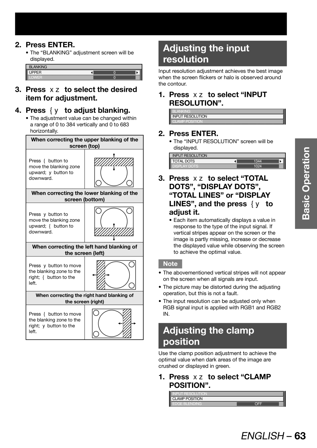
2.Press ENTER.
•The “BLANKING” adjustment screen will be displayed.
BLANKING
UPPER | 0 |
|
LOWER | 0 |
|
|
|
|
3.Press ▲▼ to select the desired item for adjustment.
4.Press ◄► to adjust blanking.
•The adjustment value can be changed within a range of 0 to 384 vertically and 0 to 683 horizontally.
When correcting the upper blanking of the
screen (top)
Press ◄ button to move the blanking zone upward; ► button to downward.
When correcting the lower blanking of the
screen (bottom)
Press ► button to move the blanking zone upward; ◄ button to downward.
When correcting the left hand blanking of
the screen (left)
Press ► button to move the blanking zone to the right; ◄ button to the left.
When correcting the right hand blanking of
the screen (right)
Press ◄ button to move the blanking zone to the right; ► button to the left.
Adjusting the input
resolution
Input resolution adjustment achieves the best image when the screen flickers or halo is observed around the contour.
1. Press ▲▼ to select “INPUT RESOLUTION”.
BLANKING
INPUT RESOLUTION
CLAMP POSITION
2. Press ENTER. |
|
|
|
|
| ||
| • The “INPUT RESOLUTION” screen will be |
| |||||
| displayed. |
|
|
|
| Operation | |
|
|
|
|
|
|
| |
| INPUT RESOLUTION |
|
|
|
| ||
| TOTAL DOTS |
|
|
|
|
|
|
|
| 1344 |
|
|
|
| |
| DISPLAY DOTS |
| 1024 |
|
|
|
|
|
|
|
|
|
| ||
3. Press ▲▼ to select “TOTAL |
| ||||||
| DOTS”, “DISPLAY DOTS”, |
| |||||
| “TOTAL LINES” or “DISPLAY | Basic | |||||
| LINES”, and the press ◄► to | ||||||
|
| ||||||
| adjust it. |
|
|
|
|
| |
| • Each item automatically displays a value in |
| |||||
| response to the type of the input signal. If |
| |||||
| vertical stripes appear on the screen or the |
| |||||
| image is partly missing, increase or decrease |
| |||||
| the displayed value while observing the screen |
| |||||
| to achieve the optimal value. |
|
|
|
|
| |
Note
•The abovementioned vertical stripes will not appear on the screen when all signals are input.
•The picture may be distorted during the adjusting operation, but this is not a fault.
•The input resolution can be adjusted only when RGB signal input is applied with RGB1 and RGB2 IN.
Adjusting the clamp
position
Use the clamp position adjustment to achieve the optimal value when dark areas of the image are crushed or displayed in green.
1. Press ▲▼ to select “CLAMP POSITION”.
INPUT RESOLUTION |
|
CLAMP POSITION |
|
EDGE BLENDING | OFF |
