Wireless connections (optional)
![]()
![]() Connecting the speakers with the optional wireless system
Connecting the speakers with the optional wireless system
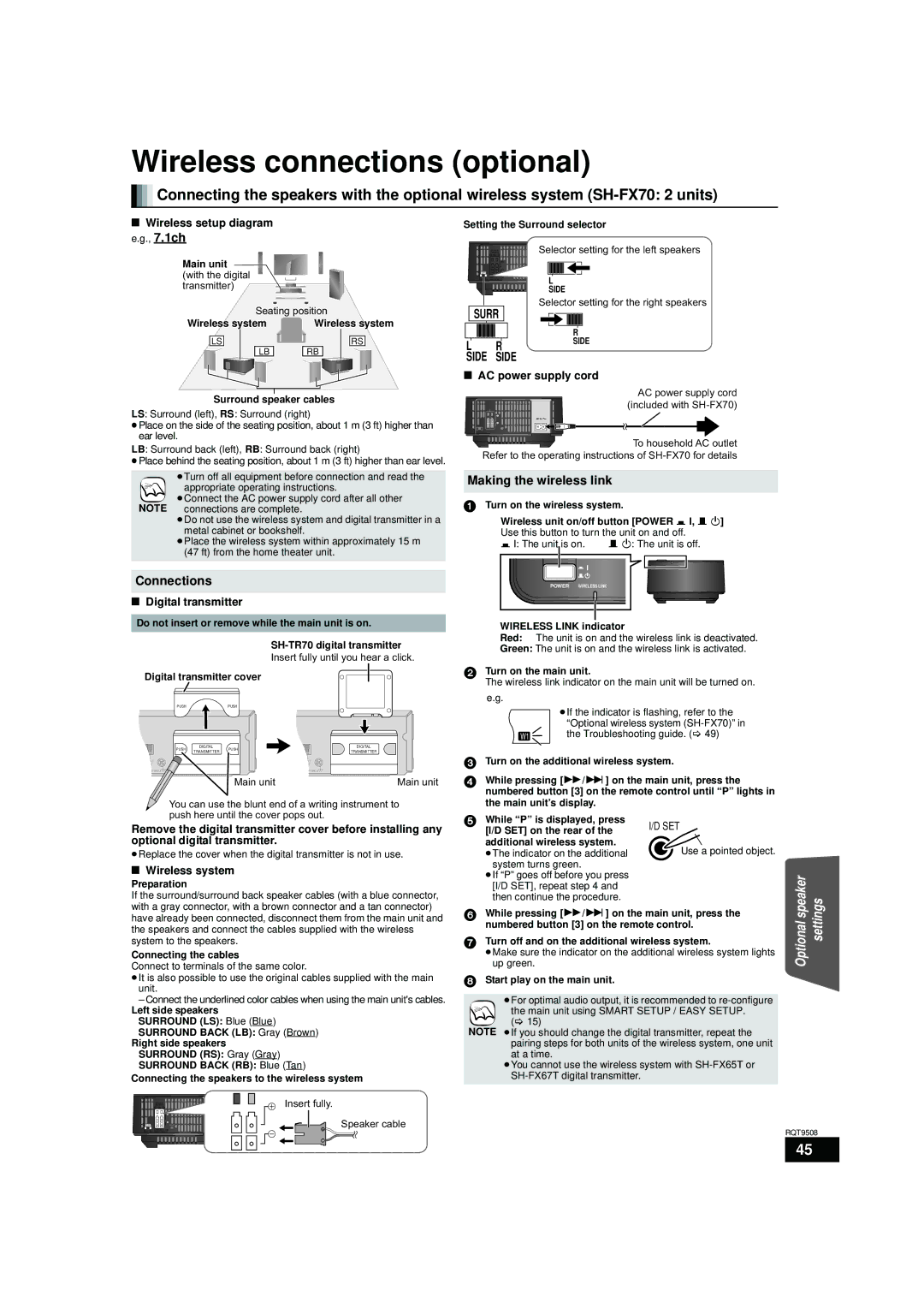
∫Wireless setup diagram e.g., 7.1ch
Main unit (with the digital transmitter)
Seating position
Wireless system |
| Wireless system | ||||||||||||
| ||||||||||||||
|
|
|
|
|
|
|
|
|
|
|
|
|
|
|
| LS |
|
|
|
|
|
|
|
|
|
| RS |
| |
| ||||||||||||||
|
|
|
|
|
|
|
|
|
|
|
|
|
| |
|
|
|
|
|
| LB |
|
| RB |
|
|
|
| |
|
|
|
|
|
|
|
|
|
|
|
| |||
|
|
|
|
|
|
|
|
|
|
|
|
|
|
|
|
|
|
|
|
|
|
|
|
|
|
|
|
|
|
|
|
|
|
|
|
|
|
|
|
|
|
|
|
|
|
|
|
|
|
|
|
|
|
|
|
|
|
|
|
Surround speaker cables
LS: Surround (left), RS: Surround (right)
≥Place on the side of the seating position, about 1 m (3 ft) higher than ear level.
LB: Surround back (left), RB: Surround back (right)
≥Place behind the seating position, about 1 m (3 ft) higher than ear level.
≥Turn off all equipment before connection and read the
appropriate operating instructions.
≥Connect the AC power supply cord after all other NOTE connections are complete.
≥Do not use the wireless system and digital transmitter in a metal cabinet or bookshelf.
≥Place the wireless system within approximately 15 m (47 ft) from the home theater unit.
Connections
∫Digital transmitter
Setting the Surround selector | |||
| LS / RB LB / RS |
| Selector setting for the left speakers |
| SPEAKERS |
|
|
| ENCEINTES |
|
|
|
|
| AC IN |
| SURR |
| I/D SET |
L | R SURROUND (3 – 6 | ) | L |
SIDE SIDE AMBIOPHONIQUES |
| ||
|
| ||
|
|
| SIDE |
Selector setting for the right speakers
SURR
|
|
| R |
L | R | SIDE | |
SIDE | SIDE |
| |
∫AC power supply cord
AC power supply cord (included with
![]() To household AC outlet Refer to the operating instructions of
To household AC outlet Refer to the operating instructions of
Making the wireless link
1Turn on the wireless system.
Wireless unit on/off button [POWER C I, B Í] Use this button to turn the unit on and off.
C I: The unit is on. | B Í: The unit is off. |
POWER WIRELESS LINK |
|
Do not insert or remove while the main unit is on. |
|
| WIRELESS LINK indicator |
| |||||||||||||||||||||
|
|
|
|
|
|
|
|
| Red: | The unit is on and the wireless link is deactivated. | |||||||||||||||
|
|
|
|
|
|
|
|
| Green: The unit is on and the wireless link is activated. | ||||||||||||||||
|
|
|
|
|
|
|
| Insert fully until you hear a click. |
| ||||||||||||||||
|
|
|
|
|
|
|
|
|
|
|
|
|
| ||||||||||||
| Digital transmitter cover |
|
|
|
|
|
|
|
|
|
| 2 Turn on the main unit. |
| ||||||||||||
|
|
|
|
|
|
|
|
|
|
|
| The wireless link indicator on the main unit will be turned on. | |||||||||||||
|
|
|
|
|
|
|
|
|
|
|
|
|
|
|
|
|
|
|
| ||||||
|
|
|
|
|
| PUSH | PUSH |
|
|
|
|
|
|
|
|
|
|
| e.g. |
|
|
|
| ||
|
|
|
|
|
|
|
|
|
|
|
|
|
|
|
|
|
|
|
| ≥If the indicator is flashing, refer to the | |||||
|
|
|
|
|
|
|
|
|
|
|
|
|
|
|
|
|
|
|
| SLP STCT DDTS | PL |
| |||
|
|
|
|
|
|
|
|
|
|
|
|
|
|
|
|
|
|
|
| SRDE. PRG |
| “Optional wireless system | |||
|
|
|
|
|
|
|
|
|
|
|
|
|
|
|
|
|
|
|
| PGMRNDRDS |
| the Troubleshooting guide. (> 49) | |||
|
|
|
|
|
|
|
|
|
|
|
|
|
|
|
|
|
|
|
| EQ W1W2 WS |
| ||||
|
|
|
|
|
| DIGITAL |
|
|
|
|
|
|
|
| DIGITAL |
|
| ||||||||
|
|
|
|
|
| DIGITAL |
|
|
|
|
|
|
|
| DIGITAL |
|
|
|
|
|
|
| |||
|
|
|
|
|
| PUSH TRANSMITTER | PUSH |
|
|
|
|
|
|
| TRANSMITTER |
|
|
|
|
|
|
| |||
|
|
|
|
|
| TRANSMITTER |
|
|
|
|
|
|
|
| TRANSMITTER |
|
|
|
|
|
|
| |||
|
|
|
|
|
|
|
|
|
|
|
|
|
|
|
|
|
|
| 3 Turn on the additional wireless system. | ||||||
AM ANT |
|
|
| AM ANT |
|
|
| ||||||||||||||||||
LOOP EXT |
|
|
| LOOP EXT |
|
|
|
|
|
|
|
|
| ||||||||||||
LOOP ANT GND |
|
|
| Main unit | LOOP ANT GND |
|
|
|
| Main unit | 4 While pressing [5/9] on the main unit, press the | ||||||||||||||
|
| ||||||||||||||||||||||||
|
|
|
|
|
|
|
|
|
|
|
|
|
|
| |||||||||||
|
|
|
|
|
|
|
|
|
|
|
|
|
|
|
|
|
|
|
| numbered button [3] on the remote control until “P” lights in | |||||
|
|
|
|
| You can use the blunt end of a writing instrument to |
| the main unit’s display. |
| |||||||||||||||||
|
|
|
|
| push here until the cover pops out. | 5 While “P” is displayed, press | | ||||||||||||||||||
Remove the digital transmitter cover before installing any | |||||||||||||||||||||||||
| [I/D SET] on the rear of the | ||||||||||||||||||||||||
optional digital transmitter. |
|
|
|
|
|
|
|
|
|
|
| additional wireless system. | Use a pointed object. | ||||||||||||
≥Replace the cover when the digital transmitter is not in use. |
| ≥The indicator on the additional | |||||||||||||||||||||||
∫ Wireless system |
|
|
|
|
|
|
|
|
|
|
| system turns green. |
| ||||||||||||
|
|
|
|
|
|
|
|
|
|
| ≥If “P” goes off before you press |
| |||||||||||||
Preparation |
|
|
|
|
|
|
|
|
|
|
|
|
| [I/D SET], repeat step 4 and |
| ||||||||||
If the surround/surround back speaker cables (with a blue connector, |
| then continue the procedure. |
| ||||||||||||||||||||||
with a gray connector, with a brown connector and a tan connector) | 6 While pressing [5/9] on the main unit, press the | ||||||||||||||||||||||||
have already been connected, disconnect them from the main unit and | |||||||||||||||||||||||||
| numbered button [3] on the remote control. | ||||||||||||||||||||||||
the speakers and connect the cables supplied with the wireless |
| ||||||||||||||||||||||||
7 Turn off and on the additional wireless system. | |||||||||||||||||||||||||
system to the speakers. |
|
|
|
|
|
|
|
|
|
| |||||||||||||||
Connecting the cables |
|
|
|
|
|
|
|
|
|
|
| ≥Make sure the indicator on the additional wireless system lights | |||||||||||||
Connect to terminals of the same color. |
| up green. |
|
|
|
| |||||||||||||||||||
≥It is also possible to use the original cables supplied with the main | 8 Start play on the main unit. |
| |||||||||||||||||||||||
unit. |
|
|
|
|
|
|
|
|
|
|
|
|
|
|
|
|
|
| |||||||
– Connect the underlined color cables when using the main unit's cables. |
| ≥For optimal audio output, it is recommended to | |||||||||||||||||||||||
Left side speakers |
|
|
|
|
|
|
|
|
|
|
|
|
| the main unit using SMART SETUP / EASY SETUP. | |||||||||||
SURROUND (LS): Blue (Blue) |
|
|
|
|
|
|
|
|
|
| (> 15) |
|
|
| |||||||||||
SURROUND BACK (LB): Gray (Brown) | NOTE ≥If you should change the digital transmitter, repeat the | ||||||||||||||||||||||||
Right side speakers |
|
|
|
|
|
|
|
|
|
|
|
|
| pairing steps for both units of the wireless system, one unit | |||||||||||
SURROUND (RS): Gray (Gray) |
|
|
|
|
|
|
|
|
|
|
| at a time. |
|
| |||||||||||
SURROUND BACK (RB): Blue (Tan) |
| ≥You cannot use the wireless system with | |||||||||||||||||||||||
Connecting the speakers to the wireless system |
|
|
| ||||||||||||||||||||||
Optional speaker | settings |
|
| SPEAKERS |
|
|
| ENCEINTES |
|
|
| LS / RB LB / RS |
|
SURR |
| I/D SET | |
L | R | SURROUND (3 – 6 | ) |
SIDE | SIDE | AMBIOPHONIQUES |
|
AC IN ![]()
Insert fully.
Speaker cable
RQT9508
45