Getting started
Control reference guide (main unit)

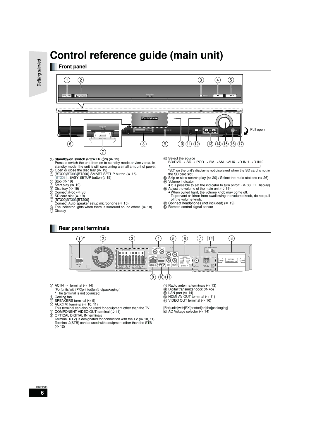
 Front panel
1 | 2 | 3 | 4 | 5 |
|
| Dock for iPod |
POWER | OPEN CLOSE | SMART SETUP |
Dock for iPod
6
7
|
|
|
| VOLUME |
| SURROUND OUTPUT |
|
|
|
SD CARD | SETUP MIC | SELECTOR | TUNE | Pull open |
|
|
8 | 9 | 10 | 11 | 12 | 13 | 14 | 15 | 16 | 17 |
1Standby/on switch (POWER Í/I) (> 19)
Press to switch the unit from on to standby mode or vice versa. In
standby mode, the unit is still consuming a small amount of power.
2Open or close the disc tray (> 19)
3[BT300] \BT303\ [BT200] : SMART SETUP button (> 15)
[BT203] : EASY SETUP button (> 15)
4Stop (> 19)
5 Start play (> 19)
6 Disc tray (> 19)
7 Connect iPod (> 30)
8 SD card slot (> 19)
9 [BT300] \BT303\ [BT200] :
Connect Auto speaker setup microphone (> 15)
:The indicator lights when there is surround sound effect. (> 18) ; Display
<Select the source
BD/DVD ) SD )IPOD ) FM )AM )AUX )D-IN 1 )D-IN 2
“SD” on the unit’s display is not displayed when the SD card is not in the SD card slot.
=Skip or
>Volume indicator
≥It is possible to set the indicator to turn on/off. (> 38, FL Display)
?Adjust the volume of the main unit (> 19)
≥When pulled hard, the volume knob may come off.
To prevent children from swallowing the volume knob, do not pull off the volume knob.
@Connect headphones (not included) (> 19)
ARemote control signal sensor

 Rear panel terminals
1 | 2 | 3 | 4 | 5 | 6 | 7 |
12
8
| SPEAKERS |
| R | AUX(TV) | L |
|
|
|
|
| |
|
|
|
|
|
|
|
|
|
| ||
|
|
|
| + |
| Y |
| PB | OPTICAL |
| |
|
|
|
|
|
|
|
|
|
|
| |
AC IN |
|
|
| - |
|
|
| PR | 2(STB) | 1(TV) |
|
5 | 2 1 | 4 3 | ( | ) AV OUT | VIDEO | COMPONENT | DIGITAL IN | 75Ω | |||
6 | 8 7 | OUT | VIDEO OUT | ||||||||
3Ω SUB- | 3Ω | R 3Ω L | R 3Ω L | R 3Ω L |
|
|
|
|
|
| FM ANT |
WOOFER CENTER | FRONT | SURROUND | SURROUND BACK |
|
|
|
|
|
|
| |
9 10 11
VOLT ADJ
110 | 220 |
127V | 240V |
LOOP EXT
AM ANT
LOOP ANT GND ![]()
![]()
![]()
DIGITAL
DIGITAL
PUSH TRANSMITTER PUSH
TRANSMITTER
1AC IN T terminal (> 14)
[For[units[with[PX[printed[on[the[packaging[
*The terminal is not polarized. 2 Cooling fan
3 SPEAKERS terminal (> 9)
4 AUX(TV) terminal (> 10, 11)
This terminal can also be used for equipment other than the TV.
5 COMPONENT VIDEO OUT terminal (> 11)
6 OPTICAL DIGITAL IN terminals
Terminal 1(TV) is designated for connection with the TV (> 10, 11) Terminal 2(STB) can be used with equipment other than the STB (> 12)
7Radio antenna terminals (> 13)
8 Digital transmitter dock (> 45)
9 LAN port (> 14)
: HDMI AV OUT terminal (> 11)
;VIDEO OUT terminal (> 10)
[For[units[with[PX[printed[on[the[packaging[
qR AC Voltage selector (> 14)
RQT9508
6