WJ-GXD900, WJ-GXE900 specifications
The Panasonic WJ-GXE900 and WJ-GXD900 are top-tier video encoders designed to meet the increasing demands of surveillance applications. These devices are essential in providing high-quality video transmission over IP networks, making them ideal for both security and monitoring purposes.One of the standout features of the WJ-GXE900 is its advanced encoding capability. It supports H.265 and H.264 compression standards, allowing for efficient bandwidth usage without compromising video quality. This technology is particularly beneficial for environments where bandwidth might be limited, as it significantly reduces the data load while maintaining impressive clarity, even in challenging lighting conditions.
The WJ-GXD900, on the other hand, is designed for high-definition video encoding. It also utilizes H.265 and H.264 technologies, but offers enhanced image processing capabilities. This includes advanced noise reduction, which helps to produce clearer images during low-light situations. Both models utilize 4K resolution support, allowing users to capture ultra-high-definition video, which is crucial for applications requiring detailed surveillance footage.
Another key characteristic of both models is their versatility in integration with IP cameras and other devices. They are compatible with a wide range of Panasonic and third-party IP cameras, ensuring that users can build a surveillance system tailored to their specific needs. This interoperability is vital for large installations where multiple camera types might be used.
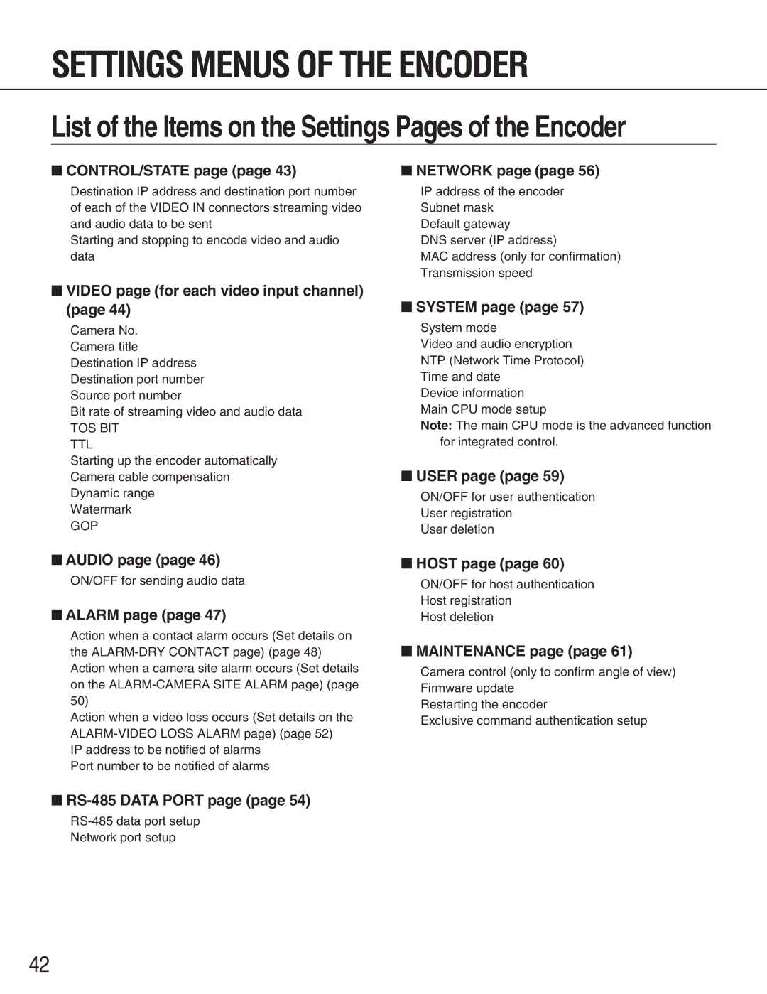
The WJ-GXE900 and WJ-GXD900 also feature intuitive web-based interfaces, simplifying the setup and configuration processes. Users can easily manage settings, stream video, and monitor performance remotely from any device with internet access. This remote management capability is increasingly important in today's fast-paced environments, where quick responses and monitoring are critical.
Additionally, both models support multiple streaming options, including the ability to deliver video to various destinations simultaneously. This feature is particularly useful for organizations needing to distribute video feeds to multiple monitors or devices, enhancing real-time surveillance capabilities.
In conclusion, the Panasonic WJ-GXE900 and WJ-GXD900 are powerful video encoders that combine advanced technology with user-friendly features. Their support for high-quality video encoding, integration flexibility, and remote management capabilities make them excellent choices for any modern surveillance system. These devices exemplify Panasonic's commitment to innovation, reliability, and high-performance solutions in the realm of security technology.
