■Connection to PS •Data Compatible Equipment
Note the following when connecting the Disk Recorder to equipment with PS• Data capability.
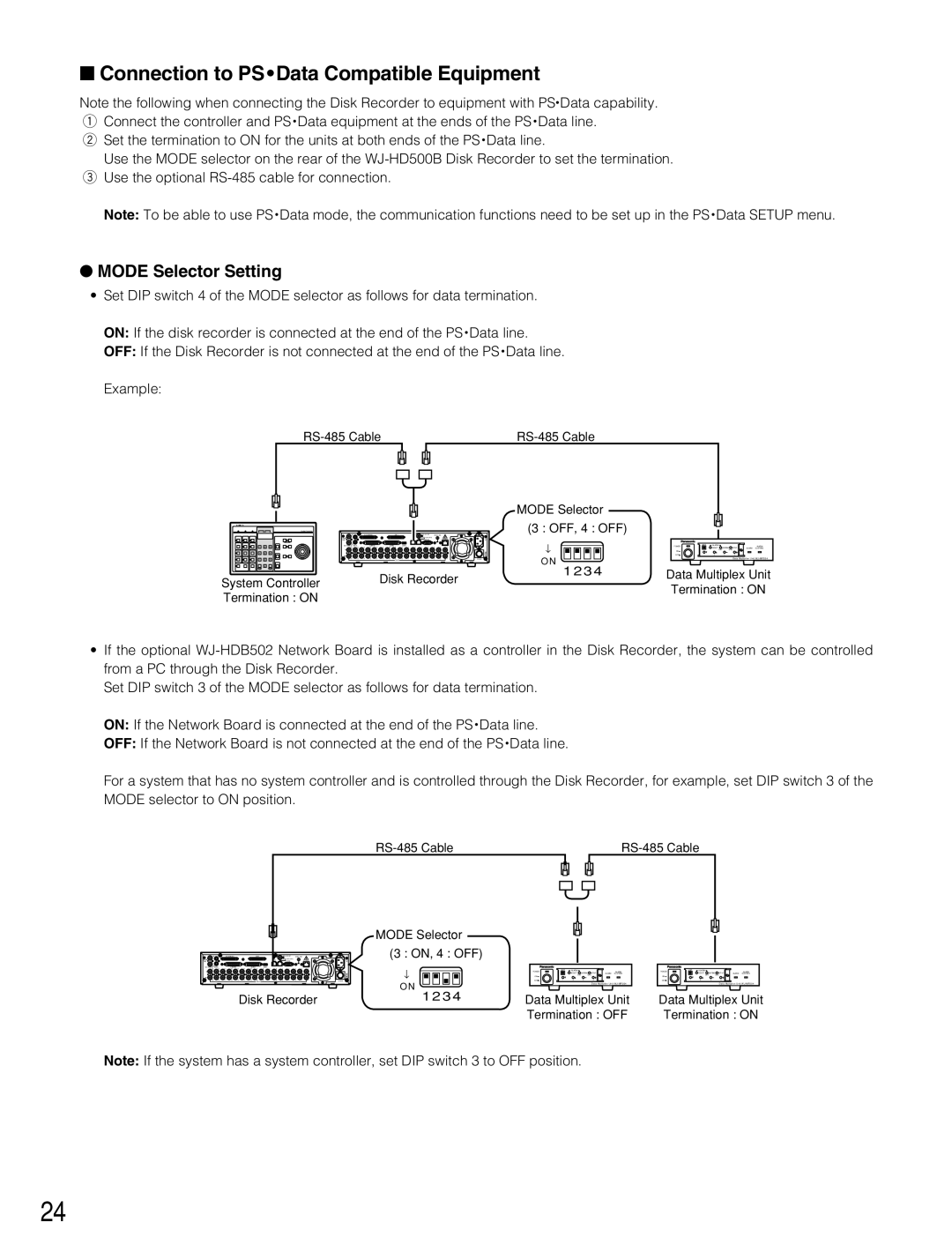
qConnect the controller and PS • Data equipment at the ends of the PS • Data line. w Set the termination to ON for the units at both ends of the PS • Data line.
Use the MODE selector on the rear of the
Note: To be able to use PS • Data mode, the communication functions need to be set up in the PS • Data SETUP menu.
●MODE Selector Setting
•Set DIP switch 4 of the MODE selector as follows for data termination.
ON: If the disk recorder is connected at the end of the PS • Data line.
OFF: If the Disk Recorder is not connected at the end of the PS • Data line.
Example:
|
|
| ||||||
|
|
|
|
|
|
|
|
|
|
|
|
|
|
|
|
|
|
|
|
|
|
|
|
|
|
|
|
|
|
|
|
|
|
|
|
|
|
|
|
|
|
| MODE Selector |
|
|
|
|
|
|
System Controller |
|
|
|
|
|
|
|
|
|
|
|
|
|
|
| (3 : OFF, 4 : OFF) |
|
|
|
|
|
|
|
|
|
|
|
|
|
|
|
|
|
|
|
|
|
| ↑ | POWER | UNIT | ALARM |
|
| ALARM |
16 | 15 | 14 | 13 | 12 | 11 | 10 | 9 | 8 | 7 | 6 | 5 | 4 | 3 | 2 | 1 |
|
|
| RESET | SUSPEND SET UP | ALARM SUSPEND | |
|
|
|
|
|
|
|
|
|
|
|
|
|
|
|
|
| ON |
|
| SET | ESC |
|
|
|
|
|
|
|
|
|
|
|
|
|
|
|
|
|
| OFF | 1 | 2 | 3 | 4 |
|
| 16 15 14 13 12 11 10 9 8 7 6 5 4 3 2 1 | O N | Data Multiplex Unit |
|
|
| |
System Controller | Disk Recorder | 1234 | Data Multiplex Unit |
| Termination : ON | ||
|
| ||
Termination : ON |
|
| |
|
|
|
•If the optional
Set DIP switch 3 of the MODE selector as follows for data termination.
ON: If the Network Board is connected at the end of the PS • Data line.
OFF: If the Network Board is not connected at the end of the PS • Data line.
For a system that has no system controller and is controlled through the Disk Recorder, for example, set DIP switch 3 of the MODE selector to ON position.
|
|
| ||||
|
|
|
|
|
|
|
|
|
|
|
|
|
|
|
|
|
|
|
|
|
|
|
|
|
|
|
|
MODE Selector
(3 : ON, 4 : OFF)
16 | 15 | 14 | 13 | 12 | 11 | 10 | 9 | 8 | 7 | 6 | 5 | 4 | 3 | 2 | 1 | ↑ |
|
|
|
|
|
|
|
|
|
|
|
|
|
|
|
| |
16 | 15 | 14 | 13 | 12 | 11 | 10 | 9 | 8 | 7 | 6 | 5 | 4 | 3 | 2 | 1 |
|
|
|
|
|
|
|
|
|
|
|
|
|
|
|
|
| O N |
|
|
|
| Disk Recorder | 1234 | |||||||||||
POWER | UNIT | ALARM |
|
| ALARM |
|
| RESET | SUSPEND SET UP | ALARM SUSPEND | |
ON |
|
| SET | ESC |
|
OFF | 1 | 2 | 3 | 4 |
|
Data Multiplex Unit
Data Multiplex Unit Termination : OFF
POWER | UNIT | ALARM |
|
| ALARM |
|
| RESET | SUSPEND SET UP | ALARM SUSPEND | |
ON |
|
| SET | ESC |
|
OFF | 1 | 2 | 3 | 4 |
|
Data Multiplex Unit
Data Multiplex Unit Termination : ON
Note: If the system has a system controller, set DIP switch 3 to OFF position.
24
