Model 2616RC
T1/E1 TDM-Digital Access Concentrator T-DAC
User Manual
Technical Support +1 301
7622 Rickenbacker Drive Gaithersburg, MD 20879 USA Tel +1 301
Summary Table of Contents
Hardware installation
Contents
3 Configuring the T-DAC for operation
Introduction
Contents
Troubleshooting and maintenance
Operation and shutdown
6 Contacting Patton for assistance
Warranty Service and Returned Merchandise Authorizations RMAs
Contents
A Compliance information
List of Figures
Model 2960 RAS Getting Started Guide
6 Symptoms 7 LED definitions
List of Tables
1 General conventions 2 Mouse conventions 3 LED definitions
4 RJ-45 plug pin-out 5 WAN cable’s 68 non-terminated twisted-pairs
Audience
About this guide
Structure
Safety when working with electricity
Precautions
General conventions
Typographical conventions used in this document
Mouse conventions
Chapter
Chapter contents
Introduction
Figure 1. Model 2616RC T-DAC
Model 2616RC T1/E1 T-DAC overview
Hardware overview
Temperature
Power system
Physical dimensions
Management services
SYSLOG Client Remote Software Upgrade via FTP
SNMP version 1 configuration management MIB TELNET via Ethernet
Frame Relay or PPP in-band management via T1/E1 DS0s
Figure 3. Model 2616RC front panel LEDs
Table 3. LED definitions
LED display
Color
Status
Chapter contents
Hardware installation
Chapter
Introduction
T-DAC blades installation
Unpacking the Model 2616RC T-DAC
Figure 4. Alignment/ESD pin and card handle
T-DAC blades installation
Connecting the Ethernet ports
Cable installation
Connecting the EIA-561 RS-232 configuration port DCE configured
68-pin SCSI to 8 RJ-45 connectors cable
Connecting the T1/E1 WAN ports
Description
Figure 13. 68-pin SCSI connector
68-pin SCSI to open end cable
Figure 12. SCSI-to-open-end WAN cable
Table 5. WAN cable’s 68 non-terminated twisted-pairs
Installing the WAN cable to a punch-down block
68-pin SCSI to 64-pin female Telco part #10-3096TM68/64-6
68-pin SCSI to open end, 6 foot cable part #10-3096TM68-6-Obsolete
Completing the hardware installation
Chapter contents
Chapter 3 Configuring the T-DAC for operation
Introduction
Configuration prerequisites
Defining static connections with DS0 mapping see page
Connecting the DB9-RJ45 adapter with the included cable
Initial configuration through the RS-232 control port
Figure 17. Connection Description window
Setting up the HyperTerminal or similar program session
Figure 18. Connect To window
3 Configuring the T-DAC for operation
Figure 20. Terminal keys configuration
Initial configuration through the RS-232 control port
7. Click on the File menu, then select Properties
11. For the user name, type superuser
Using a browser to complete Model 2616RC configuration
Home page overview
Displaying the T-DAC 2616RC web administration pages
From the Home page, the following actions can be performed
Configuring the default gateway
Example
Configuring the system clocking parameters
5. For Main Reference select wan-11
4. For Clock Reference select master1
6. For Fallback Reference select wan-22
Figure 29. System Clocking Configuration page, example
6. Click the Submit Query button shown in figure
3. For Clock Reference select secondary2 or slave3
Configuring the DS0 mapping
Solution
Examples for configuring static connections
Solution
Example
Accessing the Line Interface Settings
Configuring line settings and signaling for E1
10. Click the Submit Query button. Card 2 mapping
7. Under Dev Type B, select toH110
Figure 37. WAN Circuit Configuration page, Line Interface Settings
Configuring the E1 line interface settings
Figure 36. T1/E1 Link Activity Ports 1 - 4 page
Figure 38. Line Type pull-down menu
3. From the Line Build Out pull-down menu figure 40 select e1pulse1
Figure 39. Line Coding pull-down menu with dsx1HDB33 selected
Figure 40. Line Build Out pull-down menu with e1pulse1 selected
Accessing the Line Interface Settings
Configuring line settings and signaling for T1
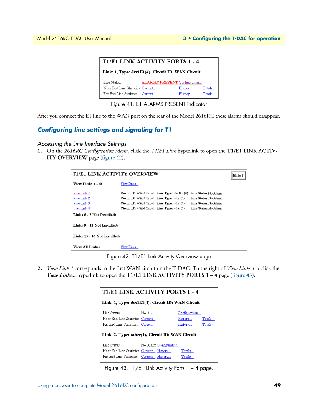
Figure 41. E1 ALARMS PRESENT indicator
Figure 42. T1/E1 Link Activity Overview page
1. From the Line Type pull-down menu figure 45 select either
Configuring the T1 line settings
dsx1ESF2 - indicates Extended SuperFrame DS1
dsx1D4 - indicates AT&T D4 format DS1
3. From the Line Build Out pull-down menu figure 47 select t1pulse0dB1
Enabling/disabling the alarm card
Backing up your configuration parameters
Saving your configuration
3 Configuring the T-DAC for operation
To import or export a configuration, do the following
Backing up your configuration parameters
Figure 51. IMPORT/EXPORT page
3 Configuring the T-DAC for operation
Backing up the configuration store in flash memory
Backing up your configuration parameters
Completing the installation
Note For information on activating and de-activating your Model 2616RC
Chapter contents
Chapter 4 Operation and shutdown
De-activating the Model 2616RC
Activating the Model 2616RC
This chapter describes how to start up and power down the Model 2616RC
Introduction
Chapter contents
Troubleshooting and maintenance
Chapter
Introduction
Note When removing the 2616RC from the chassis, follow the procedures
Location
Fault analysis
Color
Status
Table 7. LED definitions Continued
DSX1 payload loop dsx1PayloadLoop
T1/E1 port test modes
Figure 55. Line Loop
DSX1 line loop dsxLineLoop
Maintenance
Periodic maintenance
Exporting the current Model 2616RC configuration
Calibration
Maintenance
5 Troubleshooting and maintenance
Figure 56. IMPORT/EXPORT page
3. To make a back-up copy of the configuration file currently stored in your T-DAC’s flash memory
Removing the defective Model 2616RC
Importing a saved configuration
Installing the replacement Model 2616RC
Completing the installation
Chapter contents
Chapter 6 Contacting Patton for assistance
Warranty coverage
Warranty Service and Returned Merchandise Authorizations RMAs
Out-of-warranty service
Contact information
RMA numbers
Return for credit policy
Shipping instructions
Patton Electronics Company
Chapter contents
Appendix A Compliance information
Safety
Compliance
Compliance
Safety
Radio and TV Interference
Industry Canada Notice
CE Declaration of Conformity
FCC Part 68 ACTA Statement
Authorized European Representative
Chapter contents
Appendix B 68-pin SCSI-to-open-end 6-foot cable part #10-3096TM68-6
Introduction
Introduction