Model 2616RC | 5 • Troubleshooting and maintenance |
|
|
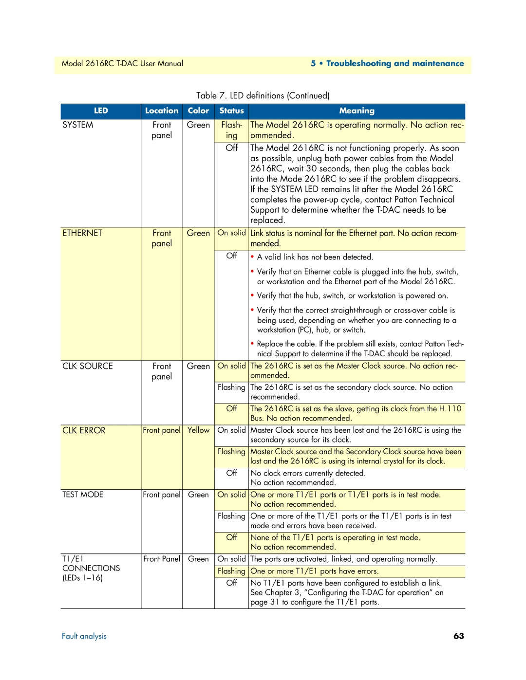
Table 7. LED definitions (Continued)
LED | Location | Color | Status | Meaning |
|
|
|
|
|
SYSTEM | Front | Green | Flash- | The Model 2616RC is operating normally. No action rec- |
| panel |
| ing | ommended. |
|
|
| Off | The Model 2616RC is not functioning properly. As soon |
|
|
|
| as possible, unplug both power cables from the Model |
|
|
|
| 2616RC, wait 30 seconds, then plug the cables back |
|
|
|
| into the Mode 2616RC to see if the problem disappears. |
|
|
|
| If the SYSTEM LED remains lit after the Model 2616RC |
|
|
|
| completes the |
|
|
|
| Support to determine whether the |
|
|
|
| replaced. |
|
|
|
|
|
ETHERNET | Front | Green | On solid | Link status is nominal for the Ethernet port. No action recom- |
| panel |
|
| mended. |
|
|
| Off | • A valid link has not been detected. |
|
|
|
| • Verify that an Ethernet cable is plugged into the hub, switch, |
|
|
|
| or workstation and the Ethernet port of the Model 2616RC. |
|
|
|
| • Verify that the hub, switch, or workstation is powered on. |
|
|
|
| • Verify that the correct |
|
|
|
| being used, depending on whether you are connecting to a |
|
|
|
| workstation (PC), hub, or switch. |
|
|
|
| • Replace the cable. If the problem still exists, contact Patton Tech- |
|
|
|
| nical Support to determine if the |
CLK SOURCE | Front | Green | On solid | The 2616RC is set as the Master Clock source. No action rec- |
| panel |
|
| ommended. |
|
|
| Flashing | The 2616RC is set as the secondary clock source. No action |
|
|
|
| recommended. |
|
|
|
|
|
|
|
| Off | The 2616RC is set as the slave, getting its clock from the H.110 |
|
|
|
| Bus. No action recommended. |
CLK ERROR | Front panel | Yellow | On solid | Master Clock source has been lost and the 2616RC is using the |
|
|
|
| secondary source for its clock. |
|
|
|
|
|
|
|
| Flashing | Master Clock source and the Secondary Clock source have been |
|
|
|
| lost and the 2616RC is using its internal crystal for its clock. |
|
|
| Off | No clock errors currently detected. |
|
|
|
| No action recommended. |
TEST MODE | Front panel | Green | On solid | One or more T1/E1 ports or T1/E1 ports is in test mode. |
|
|
|
| No action recommended. |
|
|
| Flashing | One or more of the T1/E1 ports or the T1/E1 ports is in test |
|
|
|
| mode and errors have been received. |
|
|
|
|
|
|
|
| Off | None of the T1/E1 ports is operating in test mode. |
|
|
|
| No action recommended. |
T1/E1 | Front Panel | Green | On solid | The ports are activated, linked, and operating normally. |
CONNECTIONS |
|
|
|
|
|
| Flashing | One or more T1/E1 ports have errors. | |
(LEDs |
|
| ||
|
| Off | No T1/E1 ports have been configured to establish a link. | |
|
|
| ||
|
|
|
| See Chapter 3, “Configuring the |
|
|
|
| page 31 to configure the T1/E1 ports. |
|
|
|
|
|
Fault analysis | 63 |
